Dielectric Constant of Plexiglass
Dielectric Constant of Plexiglass
In the field of industrial level measurement, the electrical properties of materials used in vessel construction, sight glasses, and protective barriers are fundamental to instrument performance. Among these properties, the dielectric constant (relative permittivity) is perhaps the most significant for electromagnetic-based sensing technologies. This article explores the dielectric constant of plexiglass (Polymethyl Methacrylate or PMMA) and its practical implications for radar and capacitance level measurement systems.
Understanding Dielectric Constant in Level Measurement
Before evaluating specific materials, it is essential to understand the physical principles of how level sensors interact with dielectrics. The dielectric constant, denoted by the Greek letter epsilon ($ε_r$), is a dimensionless number that represents the ability of a material to store electrical energy in an electric field compared to a vacuum.
Radar Measurement Principles
Radar level transmitters, whether non-contact (FMCW or Pulse) or Guided Wave Radar (GWR), rely on the reflection of electromagnetic waves. When a radar signal travels through a medium, its velocity is determined by the formula:
$$v = \frac{c}{\sqrt{\epsilon_r}}$$
Where:
* v is the velocity of the wave in the material.
* c is the speed of light in a vacuum.
* ε_r is the dielectric constant of the material.
If a radar signal must pass through a plexiglass window to reach the process media, the signal slows down as it enters the plexiglass and speeds back up as it exits. This transition causes a refractive effect and a slight time delay, which the transmitter must account for to provide an accurate distance reading. Furthermore, the difference in dielectric constants between air (ε_r ≈ 1) and plexiglass causes a partial reflection of the signal at the boundary, which can result in signal attenuation.
Capacitance Measurement Principles
Capacitance level sensors treat the probe and the vessel wall as two plates of a capacitor, with the process material acting as the dielectric. The capacitance (C) is calculated as:
$$C = \epsilon_0 \epsilon_r \frac{A}{d}$$
If a tank is constructed from plexiglass or uses a plexiglass liner, the dielectric constant of plexiglass becomes part of the measurement circuit. In these applications, the sensor must be calibrated to distinguish between the capacitance contributed by the plexiglass wall and the capacitance contributed by the rising liquid level.
The Dielectric Constant of Plexiglass
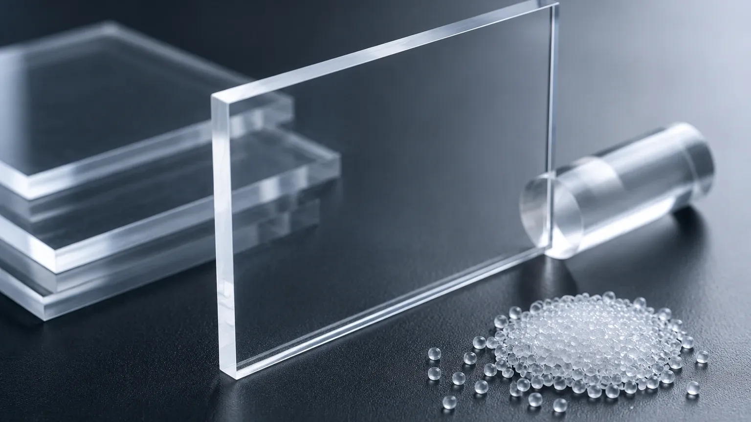
Plexiglass is a transparent thermoplastic often used as a lightweight or shatter-resistant alternative to glass. In industrial settings, it is frequently used for viewports, protective shields for sensors, or small-scale process tanks.
For engineering calculations, the dielectric constant of plexiglass typically ranges from 2.6 to 3.7. The specific value depends on several factors:
1. Frequency: The dielectric constant of PMMA is frequency-dependent. At the high frequencies used by modern radar (e.g., 24 GHz or 80 GHz), the value tends to stabilize toward the lower end of the spectrum (approximately 2.6 to 3.0).
2. Temperature: As temperature increases, the molecular mobility within the polymer increases, which can lead to slight fluctuations in the dielectric constant. However, since plexiglass has a relatively low maximum operating temperature (typically below 90°C), these shifts are usually negligible in standard applications.
3. Moisture Absorption: While plexiglass is relatively hydrophobic, it can absorb small amounts of water over time if submerged. Since water has a very high dielectric constant (ε_r ≈ 80), even minor moisture absorption can slightly increase the effective dielectric constant of the material.
Practical Selection and Comparison
When designing a level measurement system that involves a viewing window or a non-metallic barrier, engineers must compare plexiglass with other common materials. The following table provides a reference for the dielectric and physical properties relevant to sensor selection.
Material Comparison Table
| Material | Dielectric Constant (ε_r) | Max Operating Temp (°C) | Microwave Transparency | Typical Application |
| :— | :— | :— | :— | :— |
| Plexiglass (PMMA) | 2.6 – 3.7 | 70 – 90 | Good | Viewports, test tanks |
| Polycarbonate | 2.9 – 3.0 | 115 – 130 | Good | High-impact shields |
| PTFE (Teflon) | 2.1 | 260 | Excellent | Sensor wetted parts, seals |
| Borosilicate Glass| 4.0 – 5.0 | 450+ | Moderate | High-temp sight glasses |
| Polypropylene | 2.2 – 2.6 | 100 – 110 | Excellent | Chemical tank shells |
| Quartz Glass | 3.7 – 3.9 | 1000+ | High | Specialized high-temp radar |
For a comprehensive range of instruments designed to work with these materials, you can Review product options and application support at the Welk Main Page.
Installation Considerations for Radar through Plexiglass
If you are installing a radar level meter to shoot through a plexiglass window (often called a "bypass" or "window" measurement), several engineering factors must be addressed to ensure signal integrity.
1. Window Thickness and Wavelength
To minimize reflections, the thickness of the plexiglass window should ideally be a multiple of the half-wavelength of the radar signal within the material. If the window thickness causes destructive interference, the signal-to-noise ratio will drop significantly. For 80 GHz radar, which has a very short wavelength, window thickness is less critical than for 6 GHz or 24 GHz systems, but it should still be considered in the design phase.
2. Angle of Incidence
The radar should not always be mounted perfectly perpendicular to a flat plexiglass window. A slight tilt (typically 2 to 5 degrees) can help redirect the "ringing" or internal reflections away from the receiver antenna, allowing the sensor to better distinguish between the window and the actual liquid surface.
3. Condensation and Build-up
The dielectric constant of plexiglass is relatively low, which allows radar waves to pass through easily. However, if water droplets condense on the inner surface of the plexiglass, the radar signal will be reflected or scattered by the water (ε_r ≈ 80) rather than passing through to the media. In such cases, a conical or sloped window design is preferred to encourage moisture runoff.
4. Chemical Compatibility
Plexiglass is susceptible to crazing or cracking when exposed to certain solvents, alcohols, or esters. If the process media emits vapors that react with PMMA, the surface of the plexiglass will become opaque and structurally weak, which can scatter the radar signal and lead to measurement failure.
Limitations of Using Plexiglass in Level Applications
While the dielectric constant of plexiglass makes it suitable for many electronic sensing applications, there are inherent limitations:
* Thermal Expansion: Plexiglass has a high coefficient of linear thermal expansion. In outdoor installations or processes with fluctuating temperatures, the physical dimensions of a plexiglass window can change, potentially stressing the seals of the level instrument.
* UV Degradation: Standard plexiglass may yellow or become brittle over time when exposed to intense UV radiation. This change in the polymer structure can lead to a gradual shift in the dielectric properties, though the impact on radar measurement is usually secondary to the risk of structural failure.
* Pressure Constraints: Compared to borosilicate glass or stainless steel, plexiglass has low mechanical strength at elevated temperatures. It should generally be avoided in high-pressure vessel applications.
Frequently Asked Questions (FAQs)
Q: Can I use a standard ultrasonic sensor through a plexiglass window?
A: No. Unlike radar, which uses electromagnetic waves, ultrasonic sensors use mechanical sound waves. Sound waves are almost entirely reflected by solid boundaries like plexiglass. For ultrasonic measurement, the sensor must have a clear path to the media or be mounted in a way that the plexiglass is not obstructing the acoustic beam.
Q: How do I calibrate a capacitance sensor for a plexiglass tank?
A: You must perform a "dry offset" calibration. With the tank empty, the sensor measures the capacitance contributed by the plexiglass wall. This value is then tared out so that the sensor only reports changes in capacitance caused by the process material.
Q: Does the color of the plexiglass affect its dielectric constant?
A: Generally, no. Most dyes used in plexiglass are present in such small concentrations that they do not significantly alter the dielectric constant. However, metallic-flake pigments or carbon-black additives can significantly increase conductivity and dielectric loss, making the material unsuitable for radar transmission.
Q: Is plexiglass better than polycarbonate for radar windows?
A: Both have similar dielectric constants (around 2.9). Plexiglass is often preferred for its superior optical clarity and lower cost, while polycarbonate is chosen when high impact resistance or slightly higher temperature tolerance is required.
Conclusion
Understanding the dielectric constant of plexiglass is a prerequisite for successful level instrument integration in modern process environments. With a dielectric constant typically between 2.6 and 3.7, plexiglass serves as an effective medium for radar signal transmission and a stable component in capacitance-based systems, provided that temperature and chemical compatibility limits are respected.
When selecting level measurement technology, always verify the dielectric properties of all materials in the signal path. For technical assistance in choosing the right radar, ultrasonic, or hydrostatic sensors for your specific application, visit the Welk Main Page to explore our full range of industrial solutions.