Dielectric Constant Value
Dielectric Constant Value
In the field of industrial process automation, the dielectric constant value (denoted by the Greek letter εᵣ, or relative permittivity) is one of the most critical physical properties to consider when selecting and commissioning level measurement instruments. Whether using non-contact radar, guided wave radar (GWR), or capacitive level sensors, the dielectric constant of the medium directly determines the reliability, accuracy, and signal strength of the measurement. Understanding how this value interacts with electromagnetic waves is essential for engineers and plant operators to ensure stable process control.
This article provides a comprehensive technical overview of the dielectric constant value, its impact on different measurement technologies, and practical guidance for instrument selection and installation.
Understanding the Dielectric Constant Value
The dielectric constant value is a dimensionless number that represents the ratio of the permittivity of a substance to the permittivity of free space (a vacuum). In practical terms, it measures a material's ability to store electrical energy in an electric field.
From an instrumentation perspective, materials are generally classified into two categories:
1. Conductive Media: These typically have high dielectric constants (e.g., water-based liquids). They reflect electromagnetic signals very efficiently.
2. Insulating (Dielectric) Media: These have lower dielectric constants (e.g., oils, solvents, and dry powders). They allow electromagnetic waves to penetrate deeper into the material, resulting in weaker reflections.
A vacuum has a dielectric constant of exactly 1.0. Air is very close to this, at approximately 1.0006. Industrial fluids and solids range from values as low as 1.4 (such as liquid nitrogen or certain liquefied gases) to over 80 (for pure water at room temperature).
Measurement Principles and Electromagnetic Interaction
To understand why the dielectric constant value is so important, we must look at how modern level meters, particularly radar-based systems, function.
Radar Level Measurement (Non-Contact and Guided)
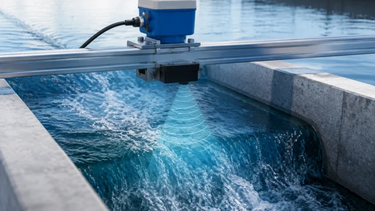
Radar level meters emit high-frequency electromagnetic pulses (typically in the GHz range). When these pulses travel through the air and hit the surface of a medium, a portion of the energy is reflected back to the sensor. The strength of this reflection is governed by the difference in the dielectric constant between the upper medium (usually air or vapor) and the lower medium (the product being measured).
The reflection coefficient (ρ) can be simplified by the following formula:
ρ = (√εᵣ – 1) / (√εᵣ + 1)
Where:
* ρ is the reflection coefficient.
* εᵣ is the dielectric constant of the medium.
As the dielectric constant value increases, the reflection coefficient increases, leading to a stronger echo. For example, water (εᵣ ≈ 80) reflects approximately 64% of the incident radar energy, while a typical hydrocarbon oil (εᵣ ≈ 2.0) reflects only about 3%. This discrepancy explains why measuring low-dielectric materials requires much more sensitive electronics and specialized antenna designs.
Capacitance Level Measurement
Capacitive sensors treat the tank and the probe as two plates of a capacitor, with the process medium acting as the dielectric. The total capacitance measured is directly proportional to the dielectric constant value of the material. If the εᵣ changes due to temperature fluctuations or chemical composition shifts, the level reading will drift unless the system is recalibrated or uses a compensation reference.
Reference Table: Common Dielectric Constant Values
Selecting the correct instrument requires knowing the εᵣ of the process media. The following table provides typical values for common industrial substances at 20°C.
| Medium | Dielectric Constant (εᵣ) | Measurement Ease |
| :— | :— | :— |
| Vacuum | 1.0 | N/A |
| Air | 1.0 | N/A |
| Liquid Nitrogen | 1.4 | Very Difficult |
| Propane (Liquid) | 1.6 | Difficult |
| Polyethylene Pellets | 1.8 – 2.0 | Difficult |
| Diesel Fuel / Fuel Oil | 2.1 | Moderate |
| Benzene | 2.3 | Moderate |
| Canola Oil | 2.4 | Moderate |
| Bitumen (Asphalt) | 2.5 – 3.0 | Easy |
| Sugar (Granulated) | 3.0 | Easy |
| Sand (Dry) | 3.0 – 5.0 | Easy |
| Ammonia (Anhydrous) | 15 – 25 | Very Easy |
| Ethanol | 24 | Very Easy |
| Methanol | 33 | Very Easy |
| Glycol | 37 | Very Easy |
| Water | 80 | Excellent |
| Sulfuric Acid | 84 | Excellent |
*Note: Values can vary based on temperature, moisture content, and purity. For comprehensive product support and instrument compatibility, visit the Main Page.*
Impact of Dielectric Constant on Instrument Selection
When the dielectric constant value of a medium is known, engineers can determine which technology will provide the most reliable data.
1. High Dielectric Media (εᵣ > 10)
Materials like water, acids, and many chemical bases are easy to measure. Standard non-contact radar (FMCW or Pulse) and ultrasonic sensors perform exceptionally well. The reflection is strong enough that even surface turbulence or foam may not significantly disrupt the signal.
2. Medium Dielectric Media (εᵣ 1.9 to 10)
Most oils, lubricants, and some dry solids fall into this range. Non-contact radar is still viable, but antenna selection becomes important. Larger horn antennas or parabolic reflectors may be needed to focus the energy and capture a sufficient return signal.
3. Low Dielectric Media (εᵣ < 1.9)
For very low εᵣ materials, such as liquefied gases or plastic pellets, standard non-contact radar may struggle to distinguish the surface echo from background noise. In these cases, Guided Wave Radar (GWR) is the preferred solution. GWR uses a physical probe (rod, cable, or coaxial) to guide the electromagnetic pulse directly to the surface, significantly reducing signal attenuation. A coaxial probe is particularly effective for low εᵣ liquids because it confines the electromagnetic field within the tube, maximizing sensitivity.
Interface Measurement and Dielectric Differences
A unique application of the dielectric constant value is in interface measurement—detecting the boundary between two immiscible liquids (e.g., oil over water).
For an interface measurement to be successful using Guided Wave Radar, two conditions must be met:
1. The upper layer must have a lower dielectric constant than the lower layer (typically the upper layer is non-conductive, like oil, and the lower layer is conductive, like water).
2. The dielectric constant value of the upper layer must be low enough (usually εᵣ < 10) to allow the radar pulse to pass through it and reflect off the interface of the second liquid.
The radar detects two echoes: the first from the surface of the top liquid and the second from the interface. The instrument then calculates the level of both layers based on the time-of-flight and the known εᵣ of the top product.

Factors Influencing Dielectric Constant Values
It is a common misconception that the dielectric constant value is a static property. Several process conditions can cause it to fluctuate:
* Temperature: For most liquids, the dielectric constant decreases as temperature increases. This is because thermal agitation makes it harder for molecules to align with an electric field.
* Moisture Content: In solids (like grain or wood chips), even a small increase in moisture can drastically increase the εᵣ because water has a very high dielectric constant. This can lead to measurement errors if the instrument is not calibrated for the specific moisture level.
* Pressure: For gases and vapors, the dielectric constant increases with pressure. In high-pressure steam applications, the εᵣ of the vapor space may rise enough to slow down the speed of the radar pulse (the propagation velocity), leading to a "distance error" where the level appears lower than it actually is. Specialized radar meters with reference reflectors are used to compensate for this effect.
Installation and Engineering Considerations
When dealing with low dielectric constant values, installation geometry becomes critical. To improve signal reliability, consider the following:
1. Stilling Wells and Bypass Chambers: For low εᵣ liquids, installing a non-contact radar inside a stilling well or using a bypass chamber can increase the signal strength by concentrating the radar energy and eliminating surface ripples.
2. Probe Selection (GWR): Use a coaxial probe for liquids with εᵣ < 1.6. For solids, a cable probe is usually required to withstand the mechanical pull-down forces, but the dielectric constant must be high enough to ensure a return signal.
3. Bottom Echo Tracking: Some advanced radar meters can use the "End of Probe" (EOP) or bottom echo to calculate the level of very low εᵣ media. If the signal passes through the medium and reflects off the tank bottom, the shift in the time-of-flight (caused by the medium's dielectric property slowing the wave) can be used to infer the level.
4. Avoid Obstructions: In low εᵣ applications, the signal is already weak. Internal tank structures like ladders, agitators, or heating coils can create "false echoes" that are stronger than the actual product reflection. Proper mapping and false echo suppression are mandatory.
Limitations and Risks
* Signal Loss: If the dielectric constant value is too low and the surface is turbulent, the radar signal may be completely lost (signal attenuation).
* Build-up: On GWR probes, if a high-dielectric material (like water-based mud) coats a probe used to measure a low-dielectric material (like oil), the sensor may only "see" the coating, leading to a false high-level reading.
* Inaccuracy in Capacitance Systems: Because capacitance measurement is directly dependent on εᵣ, any change in the chemical composition of the medium will result in a linear error in level measurement.
Frequently Asked Questions (FAQ)
Q: Can I measure the level of a vacuum?
A: No. A vacuum has a dielectric constant of 1.0, which is the same as the reference. There is no change in impedance to cause a reflection. Radar requires a medium with a dielectric constant higher than the surrounding atmosphere.
Q: What is the minimum dielectric constant value for non-contact radar?
A: Generally, modern high-frequency radars (80 GHz) can measure down to εᵣ 1.4, but this depends heavily on the distance, the antenna size, and whether the surface is calm.
Q: Does the color of the liquid affect the dielectric constant?
A: No. The dielectric constant is an electrical property related to molecular polarity and is independent of the optical properties (color or transparency) of the material.
Q: How do I find the dielectric constant of a proprietary chemical blend?
A: If the value is not in standard tables, it can be measured using a dielectric constant meter or estimated based on the proportions of the primary components. Welk's technical team can also assist in evaluating suitability based on sample data.
Conclusion
The dielectric constant value is the cornerstone of successful radar and capacitance level measurement. By understanding the εᵣ of the process media, engineers can avoid costly selection errors and ensure that the chosen instrument has the necessary sensitivity to handle the application. For low dielectric media, Guided Wave Radar and specialized installation techniques like bypass chambers remain the industry standard for reliability.
As a professional manufacturer of industrial level measurement instruments, Welk provides a wide range of solutions tailored to various dielectric environments. From high-frequency radar for volatile chemicals to robust guided wave systems for low-dielectric hydrocarbons, our technology ensures precision in the most challenging conditions. For detailed product specifications and selection guides, please refer to our Main Page.