Automated Wastewater Receiving Station
Automated Wastewater Receiving Station
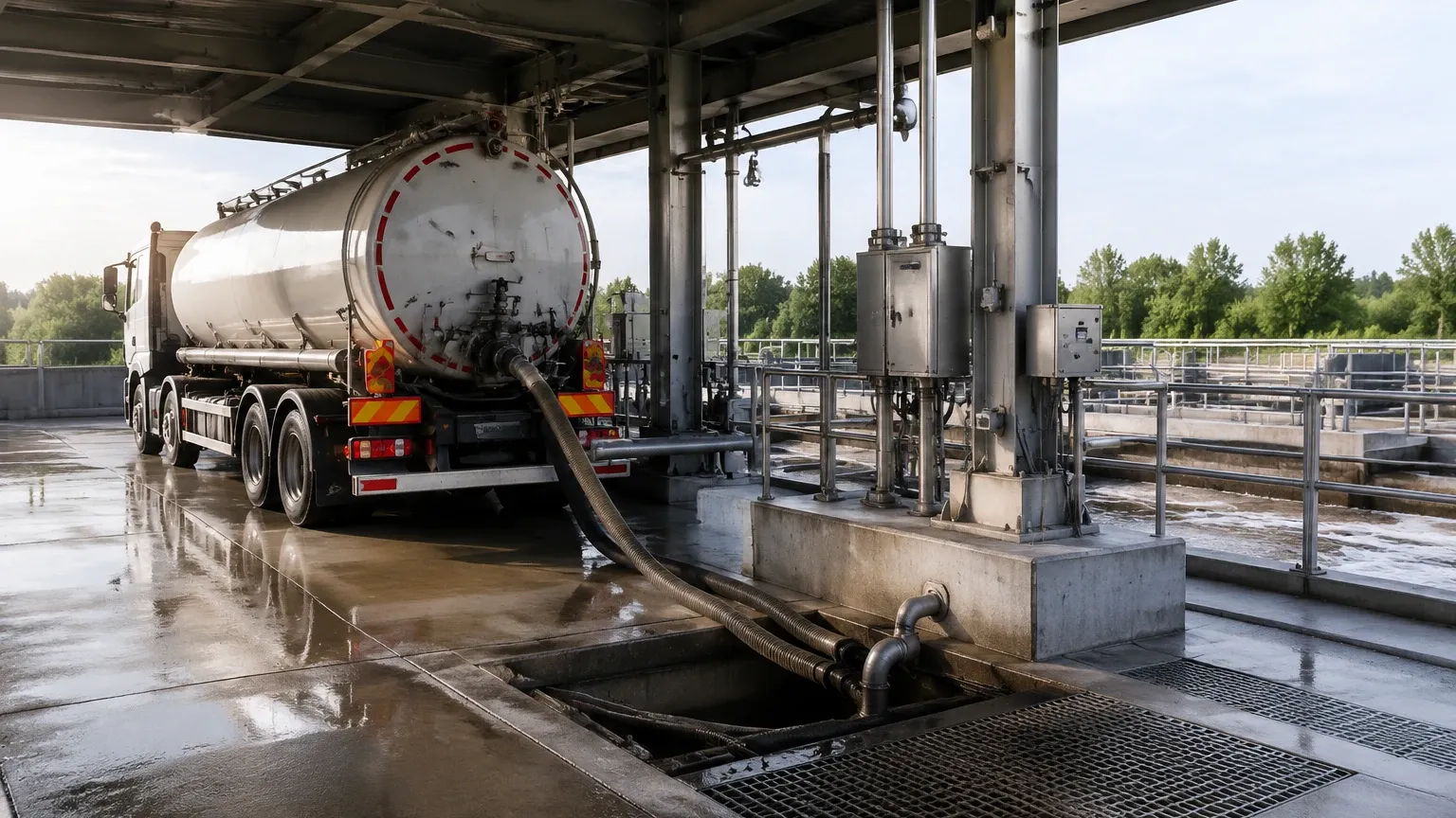
In modern municipal and industrial infrastructure, the automated wastewater receiving station serves as a critical interface between decentralized waste collection and centralized treatment facilities. These stations are designed to accept, screen, and measure septage, grease trap waste, and industrial effluents delivered by vacuum trucks. By automating the intake process, facilities can ensure accurate billing, prevent system upsets, and maintain 24/7 operational availability without the need for constant manual supervision. Central to the success of these stations is the integration of precise instrumentation, particularly level measurement technologies, which safeguard against overflows and optimize tank turnover.
The Role of Automation in Wastewater Intake
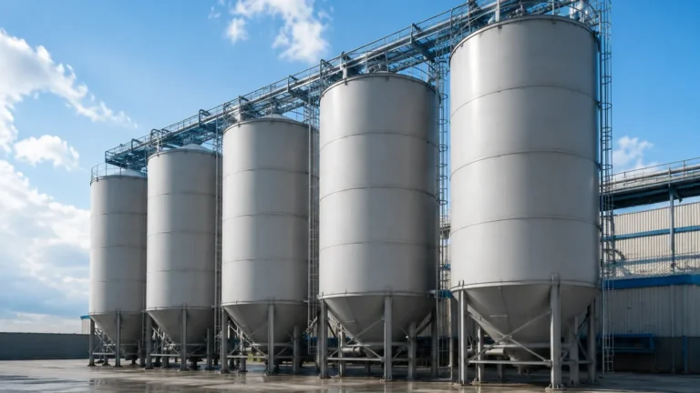
An automated wastewater receiving station typically consists of a discharge bay, a screening system to remove debris, a flow meter for volume tracking, and storage or equalization tanks. Automation allows for driver authentication via RFID or keycards, which triggers the opening of intake valves and starts the data logging process.
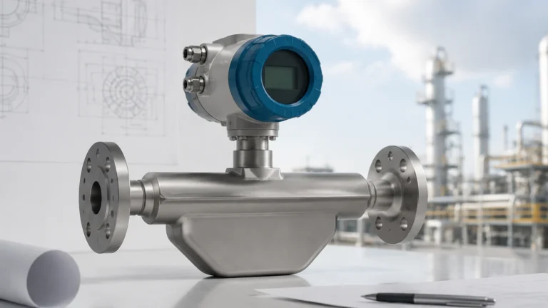
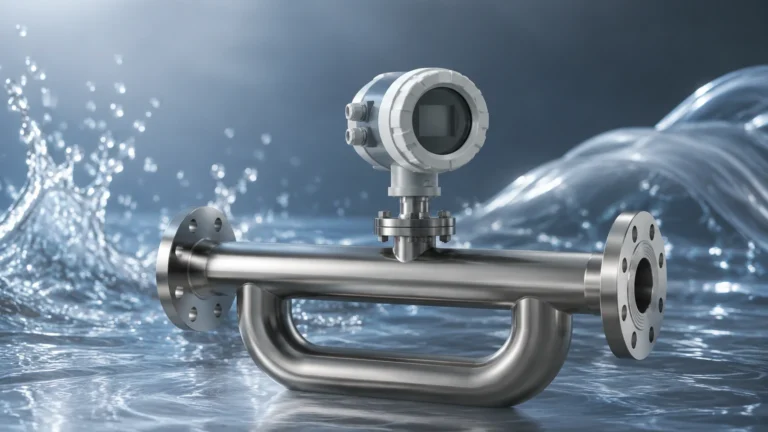
For plant operators, the primary challenge lies in managing the high variability of the incoming waste. Different loads may vary in viscosity, chemical composition, and temperature. Consequently, the level measurement systems used in these stations must be robust enough to handle turbulent surfaces, foam, and corrosive vapors. To explore the full range of instrumentation suitable for these environments, engineers often refer to the Main Page of specialized manufacturers to review product options and application support.
Measurement Principles for Level Detection
Before selecting a sensor for a receiving station, it is essential to understand the physics behind the primary technologies used in the industry. Each principle offers specific advantages depending on the physical characteristics of the wastewater.
1. Ultrasonic Level Measurement (Time-of-Flight)
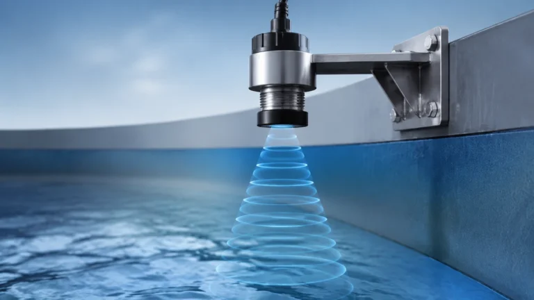
Ultrasonic sensors emit high-frequency sound pulses (typically 20 kHz to 50 kHz) that travel through the air and reflect off the liquid surface. The sensor measures the time it takes for the echo to return. Since the speed of sound in air is known, the distance to the liquid—and thus the level—can be calculated.
* Advantages: Non-contact, cost-effective, and easy to install.
* Limitations: Sensitive to heavy foam, steam, and significant temperature fluctuations, which can alter the speed of sound.
2. Radar Level Measurement (FMCW and Pulse)
Radar sensors use electromagnetic waves (often in the 26 GHz or 80 GHz range). Frequency Modulated Continuous Wave (FMCW) radar transmits a signal with a constantly changing frequency. The difference between the transmitted and received frequency is proportional to the distance.
* Advantages: Unaffected by air temperature, vacuum, or pressure. 80 GHz high-frequency radar offers a narrow beam angle, making it ideal for tanks with internal obstructions.
* Limitations: Higher initial investment than ultrasonic; requires the medium to have a dielectric constant high enough to reflect the signal.
3. Hydrostatic Pressure Measurement
This method involves placing a pressure transmitter at the bottom of the tank or submerging a probe. The sensor measures the head pressure exerted by the liquid column. Based on the formula $P = \rho gh$ (where $P$ is pressure, $\rho$ is density, $g$ is gravity, and $h$ is height), the level is determined.
* Advantages: Highly accurate for settled liquids; unaffected by foam or surface turbulence.
* Limitations: Accuracy depends on a constant liquid density. In a receiving station where waste density varies between loads, regular recalibration or density compensation may be required.
4. Magnetic Level Gauges
Magnetic gauges utilize a float containing a magnet that moves with the liquid level inside a bypass chamber. Outside the chamber, magnetic flags flip or a transmitter detects the float's position.
* Advantages: Provides a clear visual indication without power; highly reliable for high-pressure or high-temperature industrial effluents.
* Limitations: Requires a bypass pipe; not suitable for liquids with high solids content that could jam the float.
Selection Guide for Receiving Station Applications
Choosing the right technology for an automated wastewater receiving station requires balancing environmental factors against budget and maintenance capabilities. The following table provides a comparison based on typical station requirements.
| Technology | Accuracy | Resistance to Foam | Maintenance Level | Typical Application |
| :— | :— | :— | :— | :— |
| Ultrasonic | ±0.25% of range | Low to Moderate | Low | General municipal septage tanks |
| Radar (80 GHz) | ±2 mm | High | Very Low | Industrial waste with high vapor/steam |
| Hydrostatic | ±0.1% of span | Excellent | Moderate | Deep equalization basins |
| Magnetic Gauge | ±5 mm | Excellent | Moderate | Chemical-heavy industrial effluents |
Installation Considerations for Automated Stations
Proper installation is as critical as technology selection. In an automated wastewater receiving station, the physical layout of the tanks and the proximity of the discharge point can interfere with sensor performance.
* Dead Zones (Blocking Distance): All non-contact sensors (ultrasonic and radar) have a "dead zone" directly beneath the sensor face where measurements cannot be taken. For a receiving tank that may be filled nearly to the top, the sensor should be mounted on a nozzle or standpipe to move the dead zone above the maximum fill level.
* Turbulence and Inflow: Discharge from vacuum trucks often enters the tank at high velocity, creating surface turbulence. Sensors should be located away from the inlet pipe. If turbulence is unavoidable, a stilling well (a vertical pipe that stabilizes the liquid surface) should be used for hydrostatic or radar sensors.
* Vapor and Condensation: Wastewater tanks are prone to high humidity. Selecting a sensor with a high Ingress Protection (IP) rating, such as IP68, and a PTFE-faced antenna can prevent moisture buildup from affecting the signal.
* Beam Angle: When installing sensors in narrow tanks or near ladders and agitators, a narrow beam angle (common in 80 GHz radar) is preferred to avoid "false echoes" from internal structures.
Operational Limitations and Risks
While automation increases efficiency, it also introduces specific risks that must be managed through engineering controls:
1. Scaling and Coating: Wastewater often contains fats, oils, and grease (FOG). These substances can coat hydrostatic diaphragms or ultrasonic transducers. Non-contact radar is generally more resistant to coating, but periodic inspection is still necessary.
2. Signal Loss due to Foam: Heavy protein-based foam can absorb ultrasonic signals, leading to a "lost echo" error. In stations where grease trap waste is common, radar is the superior choice as it can penetrate thin foam layers or detect the top of dense foam more reliably.
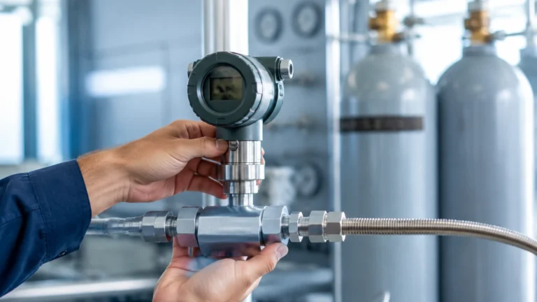
3. Data Integration: The level sensor must communicate seamlessly with the station's PLC (Programmable Logic Controller). Standard outputs like 4-20mA with HART, Modbus RTU, or Profibus are essential for integrating level data into the automated billing and safety shutdown systems.
Frequently Asked Questions (FAQs)
Q: How often should level sensors in a wastewater station be calibrated?
A: For ultrasonic and radar sensors, an annual check is usually sufficient unless the environment is extremely corrosive. Hydrostatic sensors may require bi-annual cleaning and calibration if the waste density varies significantly.
Q: Can one sensor handle both liquid level and volume?
A: Most modern transmitters allow the user to input a tank strapping table or geometry (e.g., vertical cylinder, horizontal tank with dish ends). The sensor then performs the internal calculation to output the volume in cubic meters ($m^3$) or liters.
Q: What happens if the sensor fails during a truck discharge?
A: Automated stations should always include a redundant high-level float switch. This is a simple mechanical device that acts as a hard-wired safety interlock to close the intake valve and sound an alarm, regardless of the primary sensor's status.
Conclusion and Project Confirmation
Implementing an automated wastewater receiving station significantly reduces the labor costs and environmental risks associated with manual waste handling. However, the reliability of the entire system hinges on the accuracy of its level instrumentation. Before proceeding with a project, stakeholders should confirm the following:
* Chemical Compatibility: Ensure the wetted materials of the sensor (e.g., PVDF, Stainless Steel, or Hastelloy) are compatible with the expected waste streams.
* Communication Protocols: Verify that the sensor's output matches the station's control system (SCADA/PLC).
* Environmental Extremes: Account for the maximum and minimum ambient temperatures, especially for outdoor stations in harsh climates.
By carefully evaluating the measurement principles and installation requirements, engineers can specify a solution that ensures the long-term viability of the automated wastewater receiving station. For further technical specifications and to compare different measurement models, visiting the Main Page is recommended to ensure the selected equipment meets the specific demands of the application.