Diesel Fuel Tank Monitoring System
Diesel Fuel Tank Monitoring System
In industrial and commercial operations, diesel fuel represents a significant operational expense and a critical resource for business continuity. Whether powering backup generators for data centers, fueling heavy machinery on construction sites, or maintaining fleet logistics, the ability to accurately track inventory is paramount. A robust diesel fuel tank monitoring system provides the necessary data to prevent run-outs, detect leaks, and optimize procurement cycles. This guide explores the underlying measurement technologies, selection criteria, and engineering considerations for implementing an effective monitoring solution.
Measurement Principles for Diesel Level Sensing
Before selecting a monitoring system, it is essential to understand the physical principles used to detect the fuel level. Diesel fuel presents specific challenges, including its dielectric constant (typically around 2.1), thermal expansion properties, and potential for vapor accumulation.
1. Radar Level Measurement (FMCW and Pulse)
Radar technology is widely considered the gold standard for high-precision diesel monitoring. It operates on the Time-of-Flight (ToF) principle. The sensor emits high-frequency electromagnetic waves (often in the 26GHz or 80GHz range) toward the fuel surface. These waves reflect off the liquid and return to the sensor.
* 80GHz Radar: Offers a narrow beam angle, making it ideal for tall, narrow tanks or tanks with internal obstructions like heating coils or ladders.
* Advantages: Non-contact measurement, unaffected by temperature or pressure changes, and highly accurate (up to ±1mm).
2. Ultrasonic Level Sensors
Ultrasonic sensors also use the ToF principle but utilize sound waves instead of electromagnetic waves. The sensor measures the time it takes for an ultrasonic pulse to travel to the surface and back.
* Considerations: Sound speed is affected by air temperature and vapor density. Most industrial ultrasonic sensors include integrated temperature compensation to maintain accuracy.
* Advantages: Cost-effective and easy to install for standard atmospheric tanks.
3. Hydrostatic Pressure Transmitters
Hydrostatic sensors measure the pressure exerted by the liquid column at the bottom of the tank. The relationship is defined by the formula: $P = \rho \cdot g \cdot h$, where $P$ is pressure, $\rho$ (rho) is the density of the diesel, $g$ is gravity, and $h$ is the height of the liquid.
* Implementation: A submersible pressure transducer is lowered to the bottom of the tank, or a threaded sensor is installed at the lowest point of the tank wall.
* Advantages: Highly reliable for deep tanks and underground storage tanks (USTs).
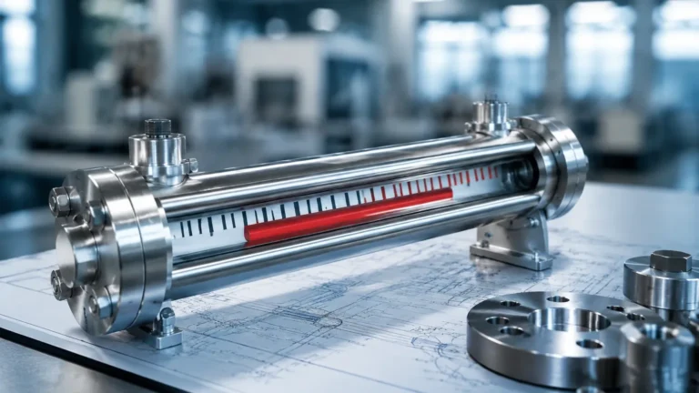
4. Magnetic Level Gauges
Magnetic level gauges consist of a float containing a permanent magnet that moves with the fuel level inside a bypass chamber or directly in the tank. This magnet actuates a series of reed switches or a resistive element in a transmitter rod.
* Advantages: Provides both a local visual indication and a remote 4-20mA or Modbus signal. It is inherently robust and suitable for high-pressure environments.
Selection Criteria for Diesel Fuel Tank Monitoring Systems
Choosing the right diesel fuel tank monitoring system requires an evaluation of the tank's physical characteristics and the operational environment. For a comprehensive overview of available hardware configurations, engineers can visit the Main Page to review product options and application support.
Tank Geometry and Location
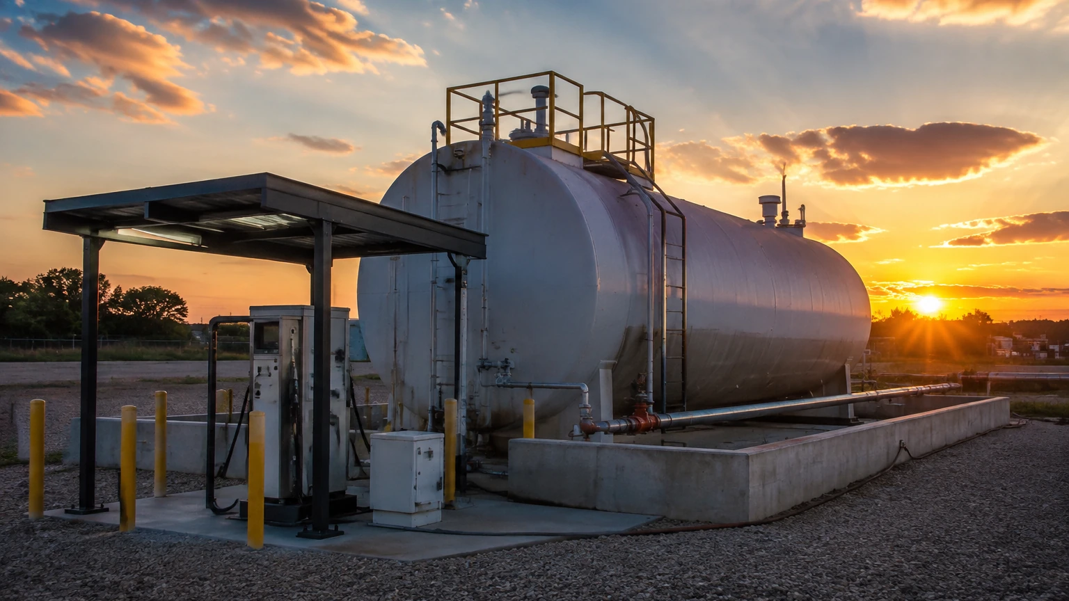
* Above-Ground Storage Tanks (ASTs): These are susceptible to ambient temperature swings. Radar or hydrostatic sensors are preferred here due to their stability.
* Underground Storage Tanks (USTs): Monitoring for leaks is a legal requirement in many jurisdictions. Hydrostatic sensors or magnetostrictive probes are commonly used for their precision in detecting small volume changes.
* Horizontal Cylindrical Tanks: Unlike vertical tanks, the volume in a horizontal tank does not have a linear relationship with the height. The monitoring system must support "strapping tables" or volume linearization formulas.
Accuracy and Reporting Requirements
| Technology | Typical Accuracy | Best Use Case |
| :— | :— | :— |
| Radar | ±1mm to ±3mm | High-value bulk storage, custody transfer |
| Ultrasonic | ±0.25% of range | Small to medium ASTs, cost-sensitive projects |
| Hydrostatic | ±0.1% to ±0.5% span | Deep tanks, underground tanks |
| Magnetic Gauge | ±5mm to ±10mm | Visual check + remote monitoring |
Connectivity and Integration
Modern systems are rarely standalone. They must integrate into broader Building Management Systems (BMS) or Industrial IoT (IIoT) platforms. Common outputs include:
* Analog (4-20mA): Standard for PLC integration.
* Digital (RS485/Modbus): Allows for daisy-chaining multiple tanks to a single controller.
* Wireless (LoRaWAN/NB-IoT): Ideal for remote sites where trenching for cables is cost-prohibitive.
Installation Considerations and Best Practices
Correct installation is as critical as sensor selection. Failure to follow engineering best practices can lead to signal interference or inaccurate readings.
1. Avoid the "Dead Zone": Every non-contact sensor (Radar and Ultrasonic) has a blocking distance or "dead zone" near the sensor face where measurements are impossible. Ensure the sensor is mounted high enough that the tank never fills into this zone.
2. Positioning: Sensors should not be mounted in the center of a tank (to avoid multiple reflections from the tank walls) or near the fill inlet (to avoid turbulence and foam during filling).
3. Nozzle Height: If using a mounting nozzle, ensure the sensor horn or transducer face extends slightly past the nozzle bottom to prevent signal ringing.
4. Venting: For hydrostatic sensors, the reference capillary in the cable must be vented to the atmosphere to compensate for changes in barometric pressure. Use a desiccant cartridge to prevent moisture from entering the vent tube.
5. Grounding: Diesel is a flammable fluid. All electronic components must be properly grounded, and sensors used in hazardous areas must carry the appropriate ATEX, IECEx, or UL certifications.
Limitations and Operational Risks
While a diesel fuel tank monitoring system significantly improves oversight, engineers must be aware of certain limitations:
* Temperature-Induced Volume Changes: Diesel fuel expands and contracts with temperature. A tank may show a different volume at midday compared to midnight, even if no fuel was added or removed. Advanced controllers use temperature probes to provide "Net Standard Volume" corrected to 15°C (60°F).
* Paraffin Wax Precipitation: In extremely cold climates, diesel can reach its "cloud point," where wax crystals form. This can coat submersible sensors or affect the buoyancy of floats.
* Surface Turbulence: During high-flow filling operations, the fuel surface can become turbulent or foamy. Sensors with advanced signal processing or the use of a stilling well can mitigate this issue.
* Condensation: In humid environments, water can condense on the face of ultrasonic sensors, temporarily blocking the signal. Radar sensors are generally less affected by this phenomenon.
Frequently Asked Questions (FAQ)
Q: Can a diesel fuel tank monitoring system detect water at the bottom of the tank?
A: Standard level sensors measure the top surface. To detect water (which settles at the bottom due to higher density), a dual-float magnetostrictive probe or an interface-capable hydrostatic sensor is required.
Q: How often should the sensors be calibrated?
A: For most industrial applications, an annual calibration check is recommended. However, hydrostatic sensors may require more frequent zero-point checks if the fuel density changes significantly between winter and summer blends.
Q: Is it possible to monitor multiple tanks with one system?
A: Yes. Multi-channel controllers can typically handle 4 to 16 tanks via Modbus or analog inputs, consolidating the data into a single dashboard or cloud portal.
Q: What is the maximum depth a hydrostatic sensor can measure?
A: Hydrostatic sensors are available for ranges from 1 meter up to 200 meters. For standard diesel storage, sensors with a 0-5m or 0-10m range are most common.
Conclusion
Implementing a professional diesel fuel tank monitoring system is a strategic investment in operational efficiency. By selecting the appropriate measurement principle—whether it be the precision of radar, the simplicity of hydrostatic pressure, or the cost-effectiveness of ultrasonic waves—facilities can ensure they have accurate, real-time data for fuel management. Proper installation, attention to environmental factors like temperature, and the use of certified hardware are the cornerstones of a reliable system. For those specifying new projects or upgrading existing infrastructure, reviewing technical specifications on the Main Page is a recommended next step to ensure the hardware aligns with the specific demands of the application.