Diesel Tank Level Indicator
Diesel Tank Level Indicator
In industrial operations, diesel fuel serves as the lifeblood for backup power systems, heavy machinery, and heating plants. Accurate inventory management is not merely a matter of convenience; it is a critical requirement for operational continuity and safety. A diesel tank level indicator provides the real-time data necessary to prevent fuel exhaustion, detect leaks, and optimize refueling schedules. Selecting the appropriate technology requires a deep understanding of the physical properties of diesel and the environmental conditions of the storage facility.
Diesel fuel presents specific challenges for level measurement, including its dielectric constant, temperature-dependent density, and the potential for foaming during high-speed filling. This guide examines the primary measurement principles used in modern indicators, provides selection criteria for various tank configurations, and outlines best practices for installation and maintenance.
Core Measurement Principles for Diesel Fuel
Before selecting a diesel tank level indicator, engineers must evaluate the underlying technology. Each principle offers distinct advantages depending on the tank's geometry and the required precision.
Hydrostatic Pressure Measurement
Hydrostatic level transmitters operate on the principle that the pressure at the bottom of a tank is directly proportional to the height of the liquid column above it. The relationship is defined by the formula: $P = \rho \times g \times h$, where $P$ is pressure, $\rho$ (rho) is the density of the diesel, $g$ is the gravitational constant, and $h$ is the height of the liquid.
Because diesel has a lower density than water (typically between 830 kg/m³ and 850 kg/m³), the transmitter must be calibrated to the specific gravity of the fuel. These sensors are often submersible (dropped into the tank) or externally mounted via a threaded connection at the tank base. They are favored for their reliability in deep tanks and their relative immunity to surface foam.
Ultrasonic (Non-Contact) Measurement
Ultrasonic sensors emit high-frequency sound pulses that travel through the air, reflect off the diesel surface, and return to the transducer. The device calculates the distance based on the time-of-flight. Since this is a non-contact method, the sensor is not subject to corrosion or clogging from fuel additives.
However, ultrasonic waves are affected by air temperature and vapor density. Most high-quality diesel tank level indicators incorporate internal temperature compensation to maintain accuracy. A critical consideration for ultrasonic technology is the "dead zone" or "blocking distance"—a small area directly beneath the sensor where measurements cannot be taken. This must be accounted for during the installation phase.
Radar (Microwave) Technology
Radar level meters utilize electromagnetic pulses rather than sound waves. There are two primary types: Guided Wave Radar (GWR) and Non-Contact Radar.
* Guided Wave Radar: Uses a probe or cable to guide the microwave signal to the fuel surface. This is highly effective for diesel because it is unaffected by turbulence or narrow tank geometries.
* Non-Contact Radar: Emits signals through the air. Diesel has a relatively low dielectric constant ($εr ≈ 2.1$), which means it reflects microwave energy less efficiently than water. Modern high-frequency radar (such as 80GHz systems) is specifically designed to handle low-dielectric liquids with high precision.
Magnetic Level Gauges
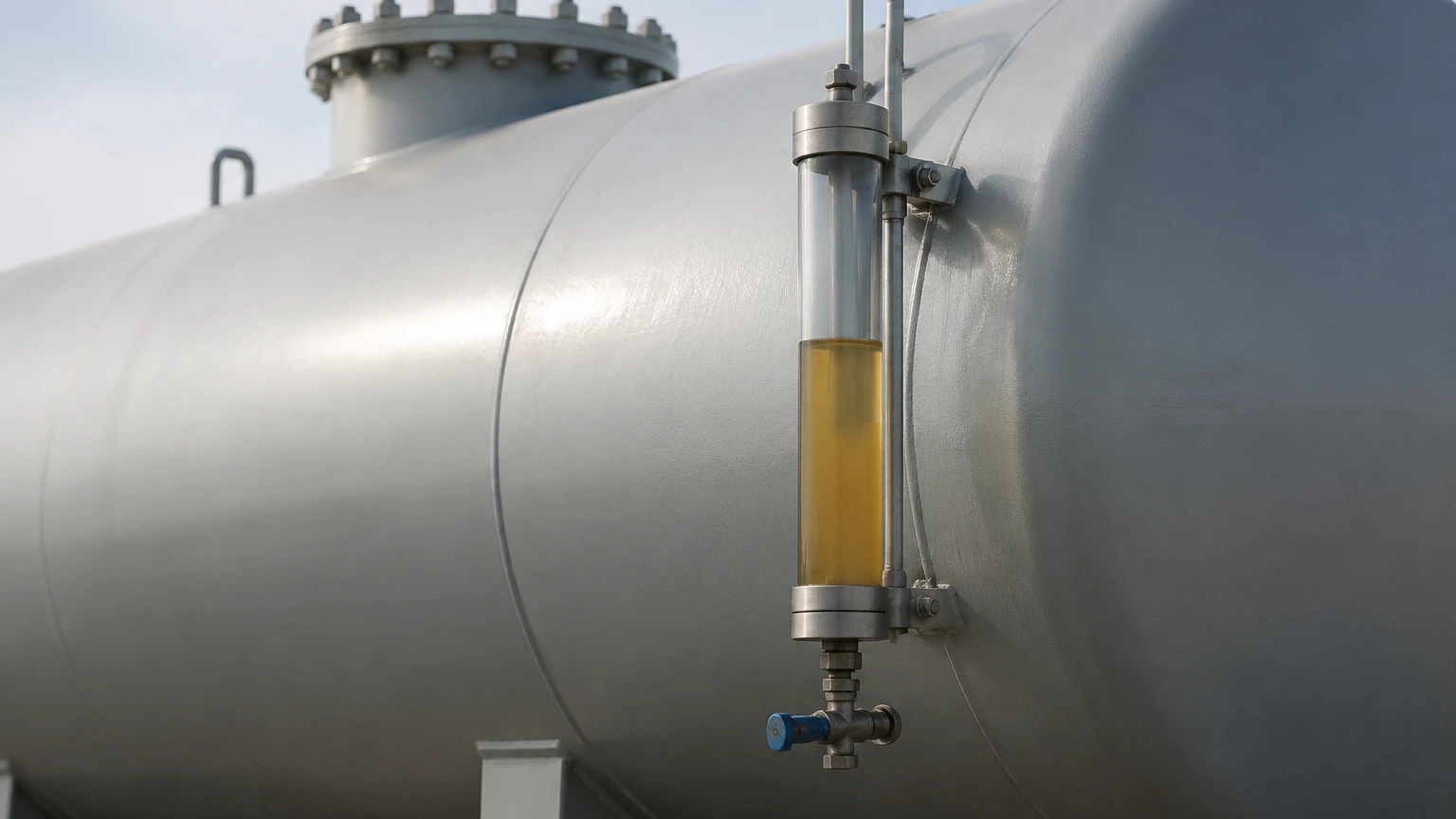
Magnetic indicators use a float containing an internal magnet that moves along a bypass chamber or a guide tube. As the diesel level changes, the float moves, flipping magnetic flags on an external scale or interacting with a reed switch array. This provides a clear visual indication without requiring an external power source, making it ideal for remote locations or as a redundant safety backup.
Selection Criteria for Diesel Storage Applications
Choosing the right indicator involves more than just selecting a technology. The specific application environment dictates the necessary specifications. For a comprehensive overview of available hardware, engineers often consult the Main Page of specialized manufacturers to compare technical data sheets.
Tank Geometry and Material
* Horizontal Cylindrical Tanks: These require indicators with volume-conversion capabilities, as the relationship between height and volume is non-linear.
* Plastic/Polyethylene Tanks: Non-contact sensors like ultrasonic or radar are often preferred to avoid penetrating the tank walls unnecessarily.
* Underground Storage Tanks (USTs): These typically require submersible hydrostatic sensors or long-probe guided wave radar due to limited overhead clearance.
Environmental Conditions
* Temperature Fluctuations: Diesel expands and contracts with temperature. If high-precision mass measurement is required, the level indicator should be paired with a temperature sensor.
* Hazardous Areas: Since diesel is combustible, the indicator must often carry ATEX, IECEx, or UL certifications for use in Class I, Division 1 or 2 environments.
* Outdoor Exposure: Sensors must be rated to at least IP67 or IP68 to withstand rain, humidity, and UV exposure.
Technical Selection Table
| Technology | Typical Accuracy | Max Range | Contact/Non-Contact | Best Use Case |
| :— | :— | :— | :— | :— |
| Hydrostatic | ±0.25% to 0.5% | Up to 200m | Contact | Deep tanks, underground storage |
| Ultrasonic | ±0.25% of range | 0.3m – 15m | Non-Contact | Standard atmospheric tanks, chemical compatibility |
| Radar (80GHz) | ±1mm to 2mm | Up to 120m | Non-Contact | High precision, low dielectric liquids |
| Magnetic Gauge | ±5mm to 10mm | Up to 6m | Contact | Visual local indication, no-power sites |
| Level Switches | N/A (Point level) | N/A | Contact | Overfill prevention, low-level alarms |
Installation and Engineering Considerations
Successful deployment of a diesel tank level indicator depends heavily on correct physical placement. Improper installation is the leading cause of signal interference and inaccurate readings.
1. Avoid the Fill Path: Never install a sensor directly under the fuel inlet. The turbulence and splashing during refueling will cause erratic readings and may damage contact-based probes.
2. Vertical Alignment: For ultrasonic and radar sensors, the transducer face must be perfectly parallel to the liquid surface. A tilt of even a few degrees can cause the signal to bounce away from the receiver, leading to "loss of echo" errors.
3. Standoff Pipes and Nozzles: If the sensor is mounted on a nozzle, the height and diameter of the nozzle must comply with the manufacturer's "beam angle" specifications. If the nozzle is too narrow or too long, the signal will reflect off the pipe walls rather than the fuel.
4. Internal Obstructions: Be mindful of internal ladders, heating coils, or baffles. For radar and ultrasonic systems, these objects can create "false echoes." Advanced indicators allow for "false echo suppression," where the software is taught to ignore reflections from fixed internal structures.
Limitations and Challenges
While modern indicators are highly advanced, they are not without limitations.
* Condensation: In humid environments, water droplets can form on the face of ultrasonic or radar transducers. While radar is generally more resistant, heavy condensation can attenuate the signal. Sensors with PTFE-coated faces are often used to shed moisture.
* Foaming: Diesel can foam significantly when pumped at high flow rates. Ultrasonic sensors may struggle with foam as it absorbs the sound pulse. Hydrostatic and guided wave radar are generally the most effective solutions for foaming applications.
* Paraffin Wax Precipitation: In extremely cold climates, diesel can reach its "cloud point," where wax crystals begin to form. This can increase the viscosity and potentially coat contact-based probes, necessitating periodic cleaning.
Frequently Asked Questions (FAQ)
Q: Can I use the same indicator for diesel and biodiesel?
A: Generally, yes, but biodiesel has a different density and dielectric constant than standard petroleum diesel. If using a hydrostatic or ultrasonic sensor, you may need to recalibrate the device to account for these physical differences.
Q: How often should a diesel tank level indicator be calibrated?
A: For standard inventory management, an annual calibration check is recommended. For custody transfer or high-precision applications, semi-annual verification may be required by local regulations.
Q: What output signals are most common for B2B integration?
A: Most industrial indicators provide a 4-20mA analog signal (often with HART protocol). For digital integration into Building Management Systems (BMS) or SCADA, Modbus RTU (RS485) is the industry standard.
Q: Is a level switch necessary if I have a continuous level indicator?
A: Yes. In many jurisdictions, a secondary, independent high-level switch is a legal requirement for overfill prevention. This ensures that if the primary indicator fails, a mechanical or separate electronic switch will trigger an emergency shut-off.
Conclusion
Implementing a reliable diesel tank level indicator is a foundational step in modern industrial fuel management. By understanding the principles of hydrostatic pressure, ultrasonic reflection, and microwave radar, engineers can select a system that balances cost, accuracy, and durability. Whether the application involves a small day tank for a generator or a massive bulk storage farm, following rigorous installation standards and accounting for the unique properties of diesel fuel will ensure long-term operational success. For those seeking specific hardware configurations and technical support, visiting the Main Page provides access to the latest innovations in level measurement technology.