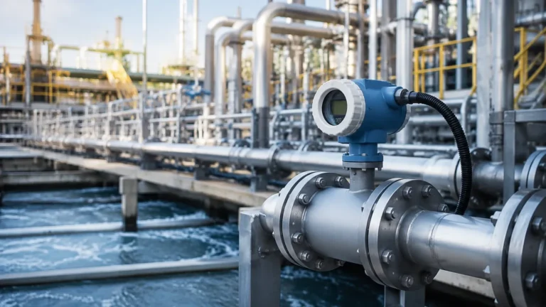
E2201
E2201
In the landscape of industrial automation and process control, the E2201 series represents a significant advancement in high-precision level measurement. As industries move toward more complex storage environments and more stringent safety requirements, the need for non-contact, highly reliable sensors has become paramount. The E2201, primarily utilized as a high-frequency radar level transmitter, addresses these needs by combining robust signal processing with the physical advantages of 80GHz frequency technology. This guide provides a comprehensive technical overview of the E2201, its operating principles, selection criteria, and practical installation strategies for engineering professionals.
Measurement Principles of the E2201 Series
Before selecting a level measurement instrument, it is essential to understand the underlying physics that govern its performance. The E2201 operates on the Frequency Modulated Continuous Wave (FMCW) principle, which is the current standard for high-end radar level sensing.
Frequency Modulated Continuous Wave (FMCW)
Unlike traditional pulsed radar, which measures the time-of-flight of a single microwave pulse, the E2201 transmits a continuous signal with a frequency that varies linearly over time (a frequency sweep). The signal travels to the surface of the medium, reflects, and returns to the sensor's antenna.
By the time the reflected signal is received, the transmitter is already emitting a signal at a different frequency. The difference between the transmitted frequency and the received frequency ($Δf$) is directly proportional to the time delay ($Δt$), and therefore directly proportional to the distance from the sensor to the material surface.
The 80GHz Advantage
The E2201 typically utilizes the 80GHz millimeter-wave band. This high frequency offers several distinct advantages over lower-frequency (6GHz or 26GHz) alternatives:
1. Narrow Beam Angle: Higher frequencies allow for a much smaller beam angle with the same antenna size. A narrow beam (often as low as 3°) minimizes interference from tank walls, internal structures like ladders or agitators, and heating coils.
2. Higher Precision: The wider bandwidth available at 80GHz allows for a higher range resolution, enabling the E2201 to achieve millimeter-level accuracy even in short-range applications.
3. Smaller Dead Zones: The E2201 can measure levels much closer to the antenna than low-frequency models, maximizing the usable volume of the vessel.
4. Better Penetration through Vapor: While high-frequency signals can be attenuated by heavy steam, the focused nature of the E2201 beam often allows it to maintain a stable signal where broader beams would lose coherence.
Technical Selection and Specifications
Choosing the correct configuration of the E2201 requires an analysis of the process medium, the vessel geometry, and the environmental conditions. The following table outlines the typical performance specifications for the E2201 series across different industrial configurations.
E2201 Selection Table
| Feature | E2201-S (Standard) | E2201-H (High Temp) | E2201-C (Corrosive) |
| :— | :— | :— | :— |
| Measuring Range | Up to 30 meters | Up to 30 meters | Up to 20 meters |
| Accuracy | ±2 mm | ±3 mm | ±2 mm |
| Frequency | 76 GHz – 81 GHz | 76 GHz – 81 GHz | 76 GHz – 81 GHz |
| Process Temp. | -40°C to 80°C | -40°C to 250°C | -40°C to 120°C |
| Process Pressure | -0.1 to 0.3 MPa | -0.1 to 2.0 MPa | -0.1 to 0.5 MPa |
| Wetted Parts | Stainless Steel / PP | Stainless Steel / PEEK | PTFE / PFA |
| Signal Output | 4-20mA / HART / RS485 | 4-20mA / HART | 4-20mA / HART |
When reviewing these options, engineers should consult the Main Page for specific model availability and custom OEM configurations that may be required for unique chemical compositions.
Installation Considerations for the E2201
Proper installation is the most critical factor in ensuring the long-term reliability of the E2201. Even the most advanced radar sensor will fail to provide accurate data if it is mounted incorrectly.
Mounting Position and Orientation
* Avoid the Center: Never mount the E2201 in the exact center of a cylindrical tank. This can cause multiple reflections to converge at the antenna, leading to signal interference and "ghost" echoes.
* Wall Distance: The sensor should be mounted at a distance from the tank wall that is at least 1/6th of the tank diameter. This prevents the beam from hitting the wall and creating false signals.
* Nozzle Height: The antenna of the E2201 should ideally extend past the bottom of the mounting nozzle. If the nozzle is too long, it can create internal reflections. If a long nozzle is unavoidable, the E2201's software can often be configured with a "False Echo Suppression" map to ignore these static reflections.
Obstruction Management
While the E2201 has a narrow beam, it is still vital to ensure that the signal path is clear of obstructions. Agitators, pipes, and reinforcement struts should be avoided. If an agitator is present, the E2201 should be mounted in a position where the beam does not intersect the path of the blades, or the signal processing must be set to average out the intermittent interference caused by the moving parts.
Environmental Protection
In outdoor installations or applications with high humidity, a sunshade or weather cover is recommended to prevent temperature fluctuations from affecting the electronics and to prevent condensation from pooling on the lens. Although the E2201 lens is often designed to be self-cleaning (using a convex shape to shed droplets), extreme conditions may require an air purge connection to keep the antenna clear of dust or crystallized vapors.
Industrial Applications of E2201
Water and Wastewater Treatment
In the water sector, the E2201 is frequently used for measuring levels in open channels, chemical storage tanks (such as sodium hypochlorite), and sludge thickeners. Its non-contact nature means it is unaffected by the corrosive or viscous nature of the fluids, reducing maintenance costs compared to hydrostatic or ultrasonic sensors that may suffer from fouling.
Chemical and Petrochemical Processing
The E2201-C variant, equipped with PTFE or PFA lining, is the preferred choice for aggressive acids and bases. Because the 80GHz signal can pass through certain non-conductive plastic tank roofs, the E2201 can sometimes be mounted outside a sealed plastic tank, measuring the level through the container wall and maintaining a total seal for hazardous materials.
Solid Materials and Powders
While radar is often associated with liquids, the E2201 is highly effective in silos containing powders, grains, or plastic pellets. The high frequency allows the signal to reflect off the uneven, sloped surfaces of solids more effectively than lower-frequency radar. This is particularly useful in the cement and food processing industries where dust clouds are common; the E2201's signal can penetrate dust that would typically block an ultrasonic sensor.

Limitations and Operational Constraints
Despite its versatility, the E2201 has specific limitations that must be addressed during the engineering phase:
1. Dielectric Constant (εr): Radar technology relies on the reflection of waves at the interface of materials with different dielectric constants. If a medium has a very low dielectric constant (e.g., certain liquefied gases or hydrocarbons with εr < 1.4), the reflection may be too weak for a standard E2201. In these cases, a stilling well or a guided wave radar might be more appropriate.
2. Heavy Foam: Thick, dense foam can absorb the microwave signal rather than reflecting it. While the E2201 can handle light surface foam, applications with consistent, heavy foam may require a different technology, such as a magnetic level gauge or a displacement transmitter.
3. Extreme Pressure: While the E2201-H can handle significant pressure, it is not designed for ultra-high-pressure reactor vessels exceeding 2.0 MPa without specialized housing.
Maintenance and Troubleshooting
The E2201 is designed for low-maintenance operation, but periodic checks are recommended to ensure system integrity.
* Signal Strength Monitoring: Most E2201 units provide a signal-to-noise ratio or echo strength metric via HART or Modbus. A gradual decrease in signal strength may indicate buildup on the antenna lens.
* Cleaning: If buildup occurs, the lens should be cleaned with a soft cloth and a solvent compatible with the wetted material (e.g., PTFE). Avoid abrasive tools that could scratch the lens surface.
* Firmware Updates: Manufacturers may release firmware updates to improve signal processing algorithms for specific difficult environments. Ensure the device is running the latest version for optimal performance.
Frequently Asked Questions (FAQ)
Q: Can the E2201 measure the interface between two liquids?
A: Generally, no. Standard non-contact radar like the E2201 is designed to detect the top surface. For liquid-liquid interface measurement (e.g., oil over water), a guided wave radar (GWR) is typically required.
Q: What is the power requirement for the E2201?
A: Most E2201 models are 2-wire loop-powered (24V DC), making them easy to integrate into existing 4-20mA control loops. 4-wire versions are also available for applications requiring high-power RS485 communication.
Q: Is the E2201 affected by vacuum?
A: No. Since radar waves do not require a medium for travel (unlike ultrasonic waves), the E2201 performs perfectly in vacuum conditions.
Q: How does the E2201 handle condensation on the antenna?
A: The E2201 often features a spherical or pointed lens design that encourages droplets to run off. Additionally, the 80GHz signal is less sensitive to small amounts of condensation compared to older 26GHz technology, though heavy condensation may still require a purge system.
For further technical documentation, CAD drawings, or to request a quote for specific industrial projects, please visit our Main Page for direct access to our engineering support team.