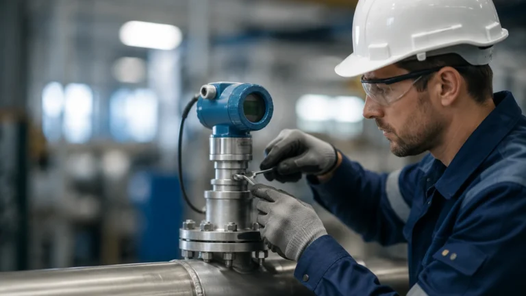
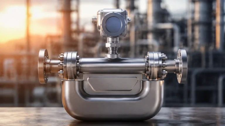
Flow Meter Verification
Flow Meter Verification
In industrial process control, the accuracy and reliability of flow measurement are critical for operational efficiency, safety, and regulatory compliance. Flow meter verification is a systematic process used to confirm that a flow meter is performing within its specified performance parameters without removing the instrument from the process line. Unlike calibration, which involves comparing the instrument against a traceable reference standard in a controlled laboratory environment, verification often relies on internal diagnostics and secondary electronic checks to ensure the device's health and measurement integrity.
For engineers and plant managers, understanding the nuances of flow meter verification is essential for maintaining high-performance systems in water treatment, chemical processing, and industrial automation. This guide explores the principles, methods, and practical considerations for implementing an effective verification strategy.
The Distinction Between Verification and Calibration
To establish a robust maintenance protocol, it is necessary to distinguish between calibration and verification. While both processes aim to ensure measurement accuracy, they serve different roles in the lifecycle of an instrument.
Calibration
Calibration is the process of comparing an instrument's output against a reference standard of known accuracy. This typically requires a flow loop or a gravimetric test rig. If the instrument deviates from the standard, it is adjusted to bring it back into specification. Calibration provides a high degree of certainty and traceability but often requires the process to be shut down and the meter to be transported to a specialized facility.
Verification
Verification is a "health check" performed in-situ. It uses the instrument’s internal diagnostic capabilities to check the integrity of the sensor, the electronics, and the output signals. Verification confirms that the meter’s components have not drifted or degraded to a point where the measurement is no longer trustworthy. It is a cost-effective way to extend the intervals between full calibrations and to meet quality management requirements such as ISO 9001.
Measurement Principles and Verification Logic
Before selecting a verification method, one must understand the underlying measurement principles of the flow meter in question. Most modern industrial flow meters, such as those utilized in advanced automation, incorporate sophisticated digital signal processing that enables self-verification.
Electromagnetic Flow Meters
Electromagnetic meters operate on Faraday’s Law of Induction. Verification for these devices involves checking the coil resistance, the insulation of the electrodes, and the integrity of the magnetic field. If the electrical properties of the coils or the insulation between the electrodes and the fluid change, the meter’s accuracy will be compromised.
Ultrasonic Flow Meters
Ultrasonic meters, particularly transit-time models, measure the time difference between pulses sent upstream and downstream. Verification involves analyzing the signal-to-noise ratio, the gain of the ultrasonic transducers, and the calculated speed of sound compared to the theoretical speed of sound for the fluid at a given temperature. A significant deviation in sound speed often indicates a change in fluid composition or a build-up of scale on the pipe walls.
Radar and Open Channel Flow
In applications involving flumes and weirs, radar level sensors are frequently used to calculate flow based on the level of the liquid. Verification here involves confirming the accuracy of the distance measurement (level) and ensuring the conversion algorithm for the specific flume geometry remains accurate. For more information on the hardware used in these configurations, engineers may consult the Main Page for detailed technical specifications.
Common Flow Meter Verification Methods
There are three primary levels of verification used in industrial environments, ranging from simple electronic checks to more complex comparative tests.
1. Built-in Self-Verification
Many high-end flow meters feature internal diagnostics that run continuously or on-demand. The transmitter monitors the health of the sensor and the internal circuitry. If any parameter falls outside of the factory-set tolerances, the system triggers an alarm. This method is highly efficient as it does not require external tools or process interruption.
2. External Verification Tools
Some manufacturers provide dedicated handheld tools or software packages that connect to the flow meter’s transmitter. These tools perform a more comprehensive suite of tests than the built-in diagnostics, checking the input/output (I/O) signals, the display, and the communication protocols. This provides a printed report that is often accepted by auditors as proof of instrument health.
3. Comparative Verification (Master Meter)
This involves placing a second, calibrated "master meter" in series with the meter being verified. This is often done using clamp-on ultrasonic flow meters, which can be attached to the outside of the pipe without breaking the seal. While this method introduces more variables, such as pipe wall thickness and fluid profile, it provides a direct cross-check of the flow measurement itself.
Key Evaluation Criteria for Verification
When conducting a flow meter verification, the following criteria must be evaluated to determine if the device is fit for continued service:
* Zero-Point Stability: For many flow technologies, the zero-point is the most critical reference. Verification must confirm that the meter reads zero when there is no flow.
* Signal Integrity: In ultrasonic and radar systems, the strength and clarity of the returned signal must be within acceptable limits. High noise levels can lead to erratic readings.
* Electrical Continuity: For magnetic flow meters, the resistance of the coils must remain stable. Changes often indicate moisture ingress or thermal damage.
* Linearity and Hysteresis: While difficult to test fully in-situ, verification software can often simulate different flow rates to check the transmitter's ability to process signals linearly across the range.
Practical Selection and Verification Matrix
The following table provides a comparison of common flow measurement technologies and their typical verification requirements in an industrial setting.
| Flow Meter Type | Primary Verification Focus | Verification Frequency | Complexity | Limitations |
| :— | :— | :— | :— | :— |
| Electromagnetic | Coil resistance, electrode insulation, transmitter I/O. | Annual | Low | Cannot detect coating on electrodes without specialized diagnostics. |
| Ultrasonic (Clamp-on) | Signal strength, sound speed, transducer alignment. | Per application/Monthly | Medium | Sensitive to pipe condition and fluid aeration. |
| Vortex | Shedder bar integrity, vibration sensor health. | Bi-annual | Medium | Mechanical wear on shedder bar is hard to detect electronically. |
| Radar (Open Channel) | Level accuracy, flume/weir geometry check. | Annual | Low | Accuracy depends heavily on the physical condition of the flume. |
| Hydrostatic (Flow) | Diaphragm integrity, pressure sensor drift. | Annual | Medium | Requires isolation of the sensor for accurate zero-checking. |
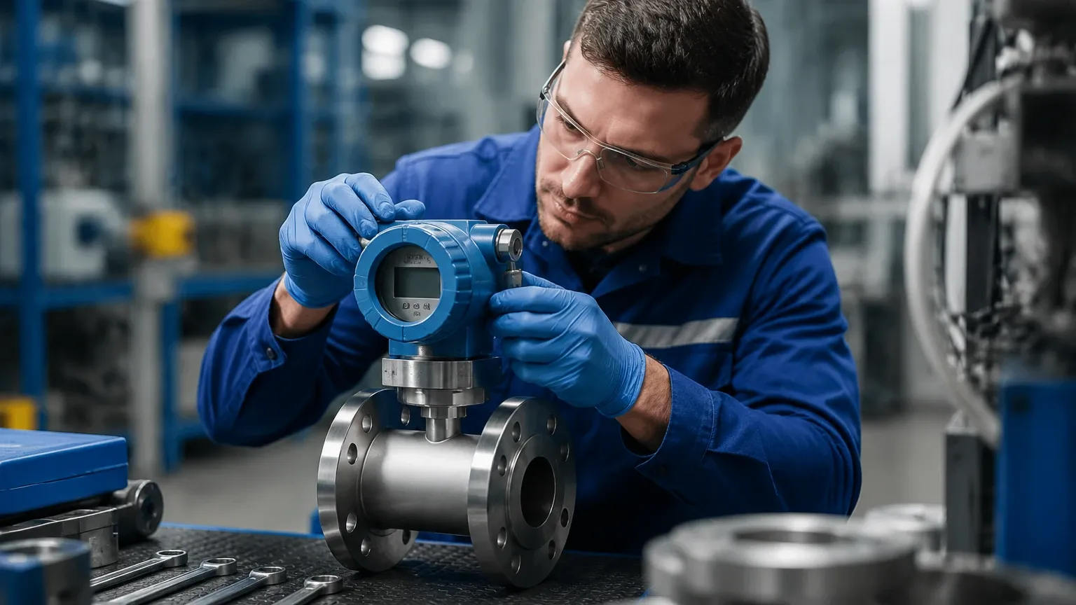
Installation Considerations for Accurate Verification
The physical installation of a flow meter significantly impacts the validity of any verification process. If a meter is installed incorrectly, it may pass an electronic verification but still provide inaccurate flow data due to hydraulic disturbances.
Straight Run Requirements
Most flow meters require a specific length of straight pipe upstream and downstream to ensure a fully developed flow profile. Typically, this is 10 to 20 diameters (DN) upstream and 5 DN downstream. If these requirements are not met, turbulence and swirl will cause measurement errors that electronic verification cannot always detect.
Fluid Properties
Verification assumes that the fluid properties (density, viscosity, conductivity) match the original design specifications. In chemical processing, if the concentration of a solution changes, a magnetic flow meter may require a different conductivity threshold. Verification should always include a check of the current fluid parameters against the meter’s configuration.
Environmental Factors
Ambient temperature, humidity, and electromagnetic interference (EMI) can affect the electronics of a flow meter. Verification should be performed under normal operating conditions to ensure that the instrument is resilient to these external factors.
Limitations and Risks of Verification
While flow meter verification is a powerful tool, it is not a perfect substitute for calibration. Engineers must be aware of the following limitations:
* Undetected Physical Wear: Electronic verification can confirm that the sensor is receiving power and sending signals, but it may not detect physical erosion of a shedder bar in a vortex meter or the thinning of a pipe wall.
* Process Fluid Changes: If the fluid being measured changes significantly (e.g., increased aeration or solid content), the meter may still be "healthy" electronically but provide an inaccurate flow rate for the new medium.
* Traceability Gaps: While verification provides a high degree of confidence, it does not always offer the same level of legal or commercial traceability required for custody transfer applications.
Frequently Asked Questions (FAQ)
Q: Can verification replace the need for laboratory calibration?
A: In many non-critical or process-monitoring applications, regular verification can significantly extend the time between calibrations. However, for custody transfer or high-stakes safety applications, periodic laboratory calibration is usually still required by law or contract.
Q: How often should flow meter verification be performed?
A: This depends on the criticality of the measurement and the stability of the process. A common schedule is to perform a basic electronic verification every six to twelve months, with a more comprehensive check every two years.
Q: What is the most common cause of verification failure?
A: In electromagnetic meters, it is often moisture ingress into the terminal box or coating on the electrodes. In ultrasonic meters, it is usually a degraded signal caused by pipe scaling or transducer aging.
Q: Do I need to stop the process to perform a verification?
A: Most modern flow meters allow for "non-intrusive" verification, meaning the process can continue to run while the electronics are checked. However, zero-point verification usually requires a "no-flow" condition, which may necessitate closing valves.
Conclusion
Flow meter verification is a vital component of modern industrial maintenance. By leveraging internal diagnostics and systematic health checks, operators can ensure that their measurement systems remain accurate and reliable over long periods. This proactive approach reduces downtime, minimizes the costs associated with unnecessary calibrations, and provides the data integrity required for advanced industrial automation. For those looking to implement or upgrade their measurement infrastructure, exploring the range of available technologies on the Main Page is a recommended next step in optimizing process performance.