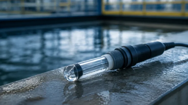
Diesel Tank Monitoring System
Diesel Tank Monitoring System
In industrial and commercial operations, diesel fuel represents both a critical utility and a significant operational expense. Whether used for emergency backup generators, heavy machinery fleets, or industrial heating processes, the ability to track fuel levels accurately is essential for maintaining continuity and controlling costs. A professional diesel tank monitoring system integrates precise level measurement sensors with data processing units to provide real-time visibility into fuel inventory, consumption rates, and potential leak or theft events.
Selecting the appropriate technology for diesel monitoring requires an understanding of the physical properties of the fuel, the geometry of the storage vessel, and the environmental conditions of the installation site. This guide examines the primary measurement principles, selection criteria, and technical considerations for engineering a reliable diesel monitoring solution.
Core Measurement Principles for Diesel Monitoring
Effective diesel tank monitoring relies on one of several physical measurement principles. Each technology offers distinct advantages depending on the tank configuration and the required precision.
1. Radar Level Measurement (Non-Contact)
Radar level meters operate on the Time-of-Flight (ToF) principle. The sensor emits high-frequency microwave pulses (typically in the 26 GHz or 80 GHz range) toward the fuel surface. These pulses are reflected back to the sensor. By measuring the time interval between emission and reception, the system calculates the distance to the fuel surface.
Because microwaves are unaffected by air temperature, pressure, or the presence of diesel vapors, radar is considered the gold standard for high-accuracy applications. 80 GHz radar units, in particular, offer a narrow beam angle, which is beneficial in tanks with internal obstructions like heating coils or ladders.
2. Ultrasonic Level Measurement
Similar to radar, ultrasonic sensors use the ToF principle but employ sound waves instead of electromagnetic pulses. A transducer emits an ultrasonic pulse that bounces off the diesel surface. The time taken for the echo to return determines the distance.
Ultrasonic systems are cost-effective and easy to install. However, they are sensitive to the speed of sound, which varies with air temperature. Most industrial ultrasonic sensors include integrated temperature compensation to mitigate this effect. They are best suited for stable environments where extreme foaming or heavy vapor concentrations are not present.
3. Hydrostatic Pressure Measurement
Hydrostatic level transmitters measure the pressure exerted by the liquid column above the sensor. In a diesel tank monitoring system, a submersible pressure transducer is lowered to the bottom of the tank, or an external sensor is mounted to a flange at the base.
The pressure (P) is proportional to the height of the liquid (h) and its density (ρ), following the formula: *P = ρgh*. Since diesel density is relatively stable but can fluctuate with temperature, high-end hydrostatic systems often include temperature sensors to adjust the density calculation dynamically.
4. Magnetic Level Gauges and Switches
For visual local indication and high/low-level alarms, magnetic level gauges are frequently used. These involve a float containing a permanent magnet that moves with the fuel level inside a bypass chamber. Outside the chamber, magnetic flaps or a follower indicate the level. Magnetic level switches can be integrated to provide dry-contact signals for overfill protection or low-fuel alerts to prevent pump cavitation.
Key Components of a Diesel Tank Monitoring System
A comprehensive monitoring solution is more than just a sensor. It typically consists of four primary layers:
1. The Sensing Element: The radar, ultrasonic, or hydrostatic transmitter that generates the raw level data.
2. Signal Processing/Local Display: A digital controller that converts the sensor signal (usually 4-20mA or RS485 Modbus) into volume units (liters or gallons) based on the tank's strapping table.
3. Communication Gateway: For remote monitoring, a gateway transmits data via Wi-Fi, Cellular (LTE-M/NB-IoT), or Ethernet to a central server.
4. Software Interface: A dashboard where operators can view historical trends, receive SMS/email alerts for low levels, and generate consumption reports.
Practical Selection Criteria
When specifying a diesel tank monitoring system, engineers must evaluate the following technical factors:
Tank Geometry and Material
* Horizontal Cylindrical Tanks: Require a volume conversion (strapping table) because the relationship between level and volume is non-linear.
* Plastic/Polyethylene Tanks: Radar signals can sometimes pass through plastic, allowing for "through-the-wall" measurement in specific configurations.
* Underground Storage Tanks (UST): Usually require submersible hydrostatic sensors or long-probe magnetostrictive sensors due to limited overhead clearance.
Environmental Conditions
* Temperature Extremes: In cold climates, diesel can wax or thicken. Sensors must be rated for low-temperature operation. Conversely, in hot environments, vapor expansion must be considered for ultrasonic sensors.
* Hazardous Areas: Diesel is a flammable liquid. In many jurisdictions, the monitoring equipment must be ATEX or IECEx certified for use in Zone 0 or Zone 1 environments.
Accuracy Requirements
If the system is used for internal inventory tracking, an accuracy of ±1% to ±3% is often sufficient. However, if the system is used for custody transfer or leak detection, high-precision radar or magnetostrictive sensors with accuracy of ±1mm (0.04 inches) may be required.
Technical Comparison Table
| Technology | Accuracy | Installation Complexity | Cost | Best Application |
| :— | :— | :— | :— | :— |
| 80GHz Radar | Excellent (±1mm) | Medium | High | Large bulk storage, high-precision needs |
| Ultrasonic | Good (±0.25%) | Low | Low-Medium | Small to medium vented tanks |
| Hydrostatic | High (±0.1-0.5%) | Medium | Medium | Underground tanks, deep wells |
| Magnetic Gauge | Moderate | High (Mechanical) | Medium | Local visual monitoring, no power sites |

Installation and Calibration Best Practices
To ensure the longevity and accuracy of a diesel tank monitoring system, follow these engineering guidelines:
1. Sensor Positioning: Avoid mounting sensors directly above the fill pipe. The turbulence and splashing during a delivery will cause erratic readings and may damage the sensor face.
2. Dead Zones (Blocking Distance): All non-contact sensors (radar and ultrasonic) have a "dead zone" directly beneath the transducer where measurement is impossible. Ensure the sensor is mounted high enough that the maximum fuel level does not enter this zone.
3. Stilling Wells: In tanks with high turbulence or internal structures, installing the sensor inside a vertical pipe (stilling well) can provide a clean, stable surface for measurement.
4. Venting: Ensure the tank is properly vented. A vacuum or pressure buildup in a sealed tank can affect hydrostatic pressure readings and, in extreme cases, collapse the tank.
5. Grounding: Proper electrical grounding is essential to prevent static discharge in fuel environments and to protect sensitive electronics from lightning surges in outdoor installations.
Operational Limitations and Risks
While modern systems are highly reliable, certain factors can introduce errors:
* Condensation: In humid environments, water can condense on the face of ultrasonic transducers, blocking the signal. Radar is generally more resistant to this.
* Foaming: High-speed diesel filling can create foam. Ultrasonic waves may be absorbed by the foam, leading to a "lost signal" error. Radar typically penetrates light foam but may still be affected by dense, thick layers.
* Tank Bottom Sludge: For hydrostatic sensors, the accumulation of sediment or "tank bottoms" can clog the sensor diaphragm. Periodic cleaning or mounting the sensor slightly above the tank floor is recommended.
Frequently Asked Questions (FAQ)
Q: Can one monitoring system handle multiple tanks?
A: Yes. Most multi-channel controllers can aggregate signals from 4 to 8 different sensors and display them on a single interface. For larger sites, networked systems can monitor hundreds of tanks across different geographic locations.
Q: How does the system detect a leak?
A: Leak detection is typically managed through "static leak testing." The system monitors the fuel level during a period of zero consumption (e.g., overnight). If the level drops beyond a specific threshold, an alarm is triggered.
Q: Is wireless monitoring secure for industrial sites?
A: Industrial-grade wireless systems use encrypted protocols (such as AES-128) to ensure that fuel data cannot be intercepted or tampered with. Cellular systems are often preferred over local Wi-Fi for their enhanced security and independence from the local IT infrastructure.
Q: Do I need to recalibrate the system after a fuel delivery?
A: No. Once the tank dimensions and fuel density are programmed into the controller, the system automatically calculates the volume based on the level. Recalibration is generally only necessary if the sensor is moved or if the fuel type changes significantly.
For engineers and facility managers looking to implement or upgrade their fuel management infrastructure, choosing a reputable manufacturer is critical. You can Review product options and application support on our Main Page to find specific instruments tailored to diesel applications, including radar and hydrostatic solutions designed for high-reliability industrial use.
By integrating a robust diesel tank monitoring system, organizations can transition from reactive fuel management to a proactive, data-driven approach, ensuring that they never run dry while optimizing their fuel procurement cycles.