Differential Pressure Gauge for Water
Differential Pressure Gauge for Water
In industrial water management and process automation, monitoring the difference in pressure between two points is often more critical than knowing the absolute pressure at either point. A differential pressure gauge for water is a specialized instrument designed to measure and display this difference, providing essential data for filtration monitoring, flow rate calculation, and liquid level measurement in pressurized vessels. As industrial systems become more complex and efficiency-driven, selecting the correct instrumentation becomes a cornerstone of operational reliability.
For engineers and facility managers, understanding the mechanical and electronic principles behind these devices is the first step toward optimizing water treatment, cooling systems, and chemical processing lines. This guide explores the technical foundations, application scenarios, and selection criteria for implementing a differential pressure gauge for water in professional environments.
Measurement Principles of Differential Pressure Gauges
The fundamental operation of a differential pressure (DP) gauge relies on the sensing of two distinct pressures, typically referred to as the High Pressure (HP) and Low Pressure (LP) sides. The instrument calculates the mathematical difference (ΔP = P1 – P2) and translates this into a visual reading or an electronic signal.
Mechanical Sensing Elements
Most mechanical DP gauges utilize one of three primary sensing elements:
1. Diaphragm Elements: This is the most common type for water applications. A flexible membrane (diaphragm) separates the two pressure chambers. When pressure on the HP side exceeds the LP side, the diaphragm deflects. This movement is linked to a pointer mechanism. Diaphragms are highly sensitive and can handle low differential ranges even under high static pressures.
2. Bellows Elements: Bellows act like an accordion. The pressure difference causes the bellows to expand or contract. These are robust and often used in applications where a larger stroke is required to drive a switch or a heavy-duty pointer.
3. Bourdon Tubes: In some DP configurations, two separate Bourdon tubes are linked to a single gear mechanism that subtracts one movement from the other. While common in standard pressure gauges, they are less frequent in high-precision differential water applications due to the complexity of the linkage.
Electronic and Piezoresistive Principles
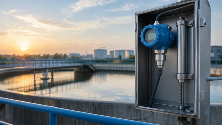
In modern industrial automation, electronic transmitters are frequently used alongside or instead of mechanical gauges. These often employ piezoresistive sensors or capacitive cells. In a piezoresistive transmitter, a silicon chip is mounted on a diaphragm. As the diaphragm bends under differential pressure, the electrical resistance of the chip changes, which is then converted into a 4-20mA or digital signal (such as HART or Modbus). These systems offer higher accuracy and the ability to integrate with PLC and SCADA systems for remote monitoring.
Key Applications in Water Systems
A differential pressure gauge for water is rarely a standalone monitor; it is usually a diagnostic tool for a specific process component. Understanding these applications helps in determining the necessary accuracy and pressure range.
1. Filtration Monitoring
This is perhaps the most ubiquitous use of DP gauges. As water passes through a filter (sand, carbon, or membrane), debris accumulates, increasing the resistance to flow. By measuring the pressure before the filter (HP) and after the filter (LP), operators can determine the "clogging state." A high differential pressure indicates that the filter requires backwashing or replacement. This prevents pump strain and ensures water quality standards are met.
2. Flow Measurement (Orifice Plate/Venturi)
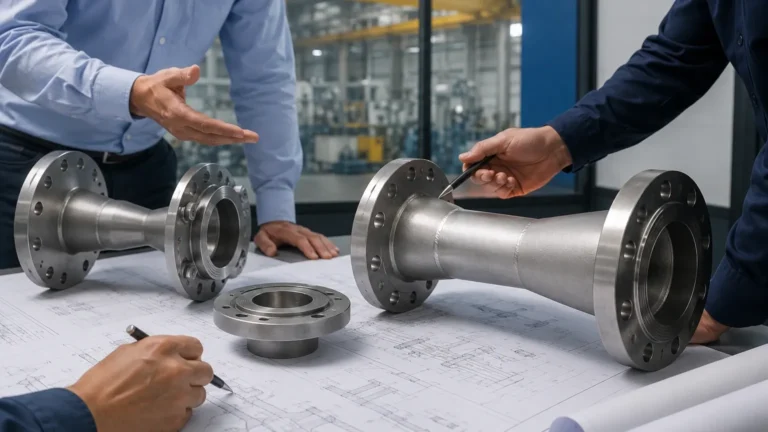
Based on Bernoulli's principle, as water flow is constricted, its velocity increases and its pressure decreases. By installing a differential pressure gauge across a flow restriction—such as an orifice plate, Venturi tube, or flow nozzle—the flow rate can be calculated. The square root of the differential pressure is proportional to the flow velocity. This method is a cost-effective alternative to electromagnetic or ultrasonic flow meters in many industrial loops.
3. Level Measurement in Pressurized Tanks
In closed tanks where the headspace is pressurized (e.g., a boiler or a chemical reactor), a standard hydrostatic level sensor cannot be used because the top pressure would skew the reading. A differential pressure gauge for water solves this by connecting the HP port to the bottom of the tank and the LP port to the top (the gas space). The gauge subtracts the head pressure of the gas, leaving only the hydrostatic pressure of the water column, which directly correlates to the liquid level.
4. Heat Exchanger Efficiency
In cooling water circuits, a DP gauge across a heat exchanger monitors for scaling or fouling. If the pressure drop across the exchanger increases over time while the flow rate remains constant, it is a clear indicator of internal mineral buildup or biological fouling, signaling the need for chemical cleaning.
Selection Criteria for Water Service
Choosing the right differential pressure gauge for water requires a detailed review of the process conditions. Failure to account for static pressure or material compatibility can lead to instrument failure or inaccurate readings.
Material Compatibility
Water is not always "just water." Depending on the source, it may contain chlorides, minerals, or treatment chemicals.
* Wetted Parts: For standard industrial water, brass or 316 stainless steel is typically sufficient. For deionized (DI) water or water with high chloride content (seawater), Monel or Hastelloy diaphragms may be required to prevent pitting corrosion.
* Seals and O-rings: EPDM is generally preferred for water service, though Viton (FKM) is used if there are traces of oils or specific chemicals in the water stream.
Static Pressure vs. Differential Range
It is vital to distinguish between the maximum working pressure (static pressure) and the differential range. For example, a system may operate at 20 bar (290 PSI) static pressure, but the filter only generates a 0.5 bar (7.2 PSI) pressure drop. The gauge must be able to withstand the 20 bar total pressure without bursting while remaining sensitive enough to accurately display the 0.5 bar difference.
Environmental Protection
Since water systems are often located in damp or outdoor environments, the gauge housing should have an appropriate Ingress Protection (IP) rating. IP65 or IP67 is standard for most industrial applications to prevent moisture and dust from entering the dial or electronic housing.
Practical Selection Table
| Feature | Diaphragm Gauge (Mechanical) | DP Transmitter (Electronic) | Piston-Type DP Gauge |
| :— | :— | :— | :— |
| Best Use Case | Local filter monitoring | SCADA integration / Control | High-pressure hydraulic/water |
| Accuracy | ±1.6% to ±2.5% FS | ±0.075% to ±0.5% FS | ±2.0% to ±5.0% FS |
| Power Required | None | 24V DC typically | None |
| Max Static Pressure | Up to 100 bar (1450 PSI) | Up to 400+ bar (5800 PSI) | Very high (up to 400 bar) |
| Signal Output | Visual Dial only | 4-20mA, HART, Modbus | Visual Dial / Switch contact |
| Cost | Moderate | High | Low to Moderate |
Installation Considerations and Best Practices
Proper installation is as important as selecting the right instrument. In water service, air bubbles and sediment are the primary enemies of accurate DP measurement.
1. Orientation and Air Venting
When measuring liquid (water), the gauge should ideally be mounted below the process tapping points. This allows any air bubbles in the impulse lines to rise back into the main pipe. If the gauge must be mounted above the tappings, air vent valves (bleed valves) must be installed at the highest point of the impulse lines to manually purge trapped air, which would otherwise cause "bouncy" or inaccurate readings.
2. Impulse Line Layout
Impulse lines (the small-diameter pipes connecting the process to the gauge) should be sloped at a gradient of at least 1:12. For water service, use 1/2-inch or 12mm tubing to reduce the risk of clogging from sediment. If the water is particularly dirty, sediment traps should be installed at the low points of the lines.
3. Use of Manifolds
A 3-valve or 5-valve manifold is highly recommended for every differential pressure gauge for water installation. The manifold allows the operator to:
* Isolate the gauge from the process for maintenance.
* Equalize the pressure between the HP and LP sides to check the zero-point calibration.
* Bleed off pressure safely before removing the instrument.
Limitations and Risks
While robust, DP gauges have specific limitations that engineers must manage:
* Overpressure Damage: If one side of the gauge is pressurized while the other is open to the atmosphere (a common mistake during commissioning), the sensing element can be permanently deformed. High-quality gauges include overpressure protection mechanisms, but these have limits.
* Freezing: In outdoor installations, water trapped in the impulse lines or the gauge chamber can freeze, expanding and rupturing the diaphragm. Heat tracing or insulation is necessary in cold climates.
* Clogging: In wastewater or untreated river water applications, the small orifices within the gauge can clog. In these cases, a chemical seal (diaphragm seal) should be used to isolate the instrument from the process media.
For those seeking specific hardware solutions or technical consultations regarding level and pressure instrumentation, you can Review product options and application support to ensure the selected equipment meets the rigorous demands of your specific industrial environment.
Frequently Asked Questions (FAQs)
Q: Can I use two standard pressure gauges instead of one differential pressure gauge?
A: While possible, it is not recommended for precision. If you have two gauges with a 2% error rate on a 10 bar scale, the combined error could be larger than the small differential pressure you are trying to measure. A dedicated DP gauge is designed to ignore the static pressure and focus only on the difference.
Q: What is the difference between a "wet/wet" and a "wet/dry" DP sensor?
A: A "wet/wet" sensor is designed to have liquid on both the HP and LP ports, which is required for a differential pressure gauge for water. A "wet/dry" sensor can only handle liquid on the HP side and is typically used for measuring liquid levels in tanks vented to the atmosphere.
Q: How often should a DP gauge be calibrated?
A: For most industrial water applications, an annual calibration check is sufficient. However, if the gauge is used for custody transfer (flow measurement) or critical safety interlocks, semi-annual calibration may be required by local regulations or quality standards.
Q: Does the length of the impulse lines affect the reading?
A: In static level or filter monitoring, length has a negligible effect on accuracy but can slow down the response time. For high-speed flow control, impulse lines should be kept as short as possible to minimize lag.
By adhering to these engineering principles and selection guidelines, organizations can ensure that their water systems operate with maximum transparency and minimal downtime. Whether monitoring a simple cooling loop or a complex treatment plant, the differential pressure gauge remains an indispensable tool in the industrial toolkit.