Natural Gas Flow Measurement
Natural Gas Flow Measurement
Natural gas flow measurement is a critical process in industrial automation, energy management, and custody transfer. Because natural gas is a compressible fluid with physical properties that fluctuate significantly based on temperature and pressure, selecting the correct measurement technology requires a deep understanding of fluid dynamics and process conditions. For engineers and facility managers, achieving high accuracy in natural gas flow measurement ensures operational efficiency, safety, and precise billing.
In industrial environments, natural gas is rarely a pure substance; it often contains varying concentrations of methane, ethane, propane, and trace impurities. These variations, combined with the high-pressure environments typical of pipelines and storage facilities, necessitate robust instrumentation that can provide repeatable data under fluctuating conditions.
Understanding the Fundamentals of Natural Gas Flow Measurement
Before selecting a flow meter, it is essential to distinguish between actual flow and standard flow.
* Actual Flow (Actual Cubic Meters, ACm): This is the volume of gas passing through the meter at the operating temperature and pressure.
* Standard Flow (Standard Cubic Meters, SCM): This is the volume the gas would occupy at a defined reference temperature and pressure (typically 15°C/60°F and 101.325 kPa/14.7 psi).
Since natural gas is highly compressible, a change in pressure from 1 bar to 10 bar will drastically reduce its volume while its mass remains constant. Most industrial applications require mass flow or standardized volume flow for reporting and billing. Therefore, many flow measurement systems incorporate pressure and temperature compensation—often referred to as "PT compensation"—to convert actual volume into standard volume using the Ideal Gas Law or more complex equations of state like AGA-8 or GERG-2008.
Key Technologies for Natural Gas Flow Measurement
Several technologies are employed for measuring gas flow, each with distinct principles of operation, advantages, and limitations.
1. Differential Pressure (DP) Meters
Differential pressure measurement is one of the oldest and most widely used methods. It relies on Bernoulli’s principle, which states that as the speed of a moving fluid increases, the pressure within the fluid decreases. By placing a restriction in the pipe, such as an orifice plate, a pressure drop is created. The square root of this pressure difference is proportional to the flow rate.
* Advantages: Well-understood standards (ISO 5167), no moving parts, and relatively low cost for large pipe sizes.
* Limitations: Limited turndown ratio (typically 4:1), high permanent pressure loss, and sensitivity to edge wear on the orifice plate.
2. Turbine Flow Meters
Turbine meters utilize a multi-bladed rotor mounted in the gas stream. The gas flow causes the rotor to spin at a speed proportional to the velocity of the gas. This mechanical rotation is sensed electromagnetically or mechanically to determine the flow rate.
* Advantages: High accuracy for custody transfer, excellent repeatability, and suitable for high-pressure applications.
* Limitations: Moving parts are subject to wear, requires clean gas to prevent bearing damage, and introduces pressure drop.
10
3. Vortex Shedding Flow Meters
Vortex meters operate on the Karman Vortex Street principle. When gas flows past a non-streamlined "shredder bar," vortices are shed alternately on each side. The frequency of these vortices is directly proportional to the gas velocity.
* Advantages: No moving parts, wide temperature/pressure range, and excellent long-term stability.
* Limitations: Requires a minimum Reynolds number to function, and sensitive to pipe vibration.
4. Thermal Mass Flow Meters
These meters measure the heat dissipation from a heated sensor immersed in the gas stream. As gas flows past the sensor, it carries away heat. The amount of energy required to maintain a specific temperature difference is proportional to the mass flow rate.
* Advantages: Measures mass flow directly without additional PT compensation, high sensitivity to low flow rates, and negligible pressure drop.
* Limitations: Accuracy is highly dependent on knowing the exact gas composition; moisture or droplets on the sensor can cause significant errors.
5. Ultrasonic Flow Meters (Transit-Time)
Ultrasonic meters use acoustic transducers to send sound pulses upstream and downstream. The difference in transit time between the two pulses is used to calculate the gas velocity.
* Advantages: Extremely high accuracy, no pressure drop, no moving parts, and bi-directional measurement capability.
* Limitations: High initial capital cost and requires complex signal processing.
Selection Criteria for Industrial Applications
Choosing the right instrument for natural gas flow measurement involves balancing accuracy requirements against installation constraints and budget. The following table provides a practical comparison of common technologies.
| Technology | Typical Accuracy | Turndown Ratio | Maintenance Level | Best Use Case |
| :— | :— | :— | :— | :— |
| Differential Pressure | ±1.0% to 2.0% | 4:1 | Medium | Large pipes, stable flows |
| Turbine | ±0.5% to 1.0% | 10:1 to 20:1 | High | Custody transfer, clean gas |
| Vortex | ±1.0% | 15:1 | Low | High-velocity steam or gas |
| Thermal Mass | ±1.0% | 100:1 | Low | Leak detection, low pressure |
| Ultrasonic | ±0.1% to 0.5% | 50:1 | Low | High-value custody transfer |
| Coriolis | ±0.5% | 20:1 | Low | Direct mass flow, high precision |
Installation Best Practices and Piping Requirements
To ensure the accuracy of natural gas flow measurement, the physical installation must adhere to specific engineering guidelines. Flow profiles must be fully developed and free from swirls or turbulence caused by upstream components.
1. Straight Pipe Runs: Most meters require a minimum length of straight pipe upstream and downstream. A common rule of thumb is 10 diameters (10D) upstream and 5 diameters (5D) downstream, though this varies by technology. For example, turbine and ultrasonic meters are highly sensitive to turbulence and may require longer runs or flow conditioners.
2. Flow Conditioners: If the installation site lacks sufficient space for long straight runs, flow conditioners (perforated plates or tube bundles) can be used to stabilize the flow profile.
3. Orientation: For gas measurement, meters should ideally be installed in horizontal lines. If installed vertically, the flow should generally be upward to ensure any potential condensate does not pool at the sensor head.
4. Avoid Low Points: Flow meters should not be installed at the lowest point of a piping system where moisture and contaminants (condensate or compressor oil) tend to accumulate.
Managing Risks: Contamination and Compensation
Natural gas flow measurement faces two primary operational risks: gas composition changes and physical contamination.
Gas Composition Shifts: Thermal mass meters and DP meters are calibrated for a specific gas density or thermal conductivity. If the methane-to-ethane ratio changes significantly, the meter will report an error. In these cases, a gas chromatograph is often used in conjunction with the flow meter to provide real-time composition data for compensation.
Moisture and Particulates: Natural gas "at the wellhead" or in gathering lines is often "wet," containing water vapor and liquid hydrocarbons. These liquids can coat sensors or damage turbine blades. Using high-quality filtration and separation upstream of the measurement point is essential. For applications involving storage tanks or separators, monitoring liquid levels is equally important to prevent carryover into the gas lines. You can Review product options and application support on the Welk Main Page to see how level instrumentation supports the overall efficiency of gas processing systems.
The Role of Level Measurement in Gas Processing Systems
While flow measurement tracks the movement of gas, level measurement is indispensable in the infrastructure that supports it. Natural gas is often stored in liquid form (LNG) or processed in separators where gas, oil, and water are divided.
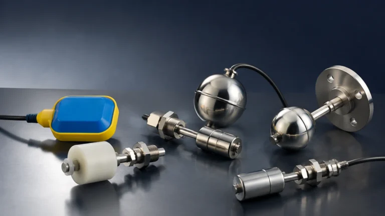
In a 3-phase separator, accurate level measurement of the liquid interface is required to ensure that the gas outlet remains clear of liquid. If the liquid level rises too high, droplets can enter the gas stream, leading to "slugging" which can destroy turbine flow meters or cause massive inaccuracies in DP and ultrasonic systems. Welk provides advanced radar and ultrasonic level sensors specifically designed for these high-pressure, hazardous environments, ensuring that the gas entering the flow measurement stage is as dry and clean as possible.
Project Checklist: Confirming Your Requirements
Before finalizing a natural gas flow measurement solution, project engineers should confirm the following data points:
* Maximum and Minimum Flow Rates: Ensure the meter’s turndown ratio covers the entire operating range.
* Process Pressure and Temperature: Verify that the meter body and sensors are rated for the maximum possible excursion limits.
* Gas Composition: Determine if the gas is "dry" or "wet" and if the composition is stable.
* Accuracy Requirements: Is this for internal process control (lower accuracy needed) or custody transfer/billing (highest accuracy needed)?
* Hazardous Area Ratings: Ensure the equipment meets ATEX, IECEx, or local equivalent certifications for explosive gas atmospheres.
* Connectivity: Confirm the output requirements (4-20mA, HART, Modbus, or Foundation Fieldbus) for integration into the plant’s PLC or SCADA system.
Frequently Asked Questions (FAQ)
Q: How often should a natural gas flow meter be calibrated?
A: For custody transfer, calibration is typically required annually or bi-annually. For process control, a check every 2-3 years may suffice, depending on the stability of the gas and the presence of contaminants.
Q: Can I use an ultrasonic meter for wet gas?
A: Standard transit-time ultrasonic meters struggle with wet gas because liquid droplets scatter the sound signals. Specialized multi-path ultrasonic meters or those designed specifically for wet gas applications are required in these scenarios.
Q: Why is my thermal mass meter reading higher than expected?
A: This is often caused by moisture. If liquid droplets hit the heated sensor, they absorb a significant amount of energy to evaporate, which the meter interprets as a very high gas flow.
Q: Do I need a flow computer?
A: If your flow meter does not have built-in PT compensation and you need standardized volume or mass flow, a separate flow computer is necessary to integrate inputs from the flow meter, pressure transmitter, and temperature sensor.
By carefully evaluating the measurement principle and adhering to strict installation standards, industrial operators can ensure that their natural gas flow measurement systems provide the reliable data necessary for safe and profitable operations.