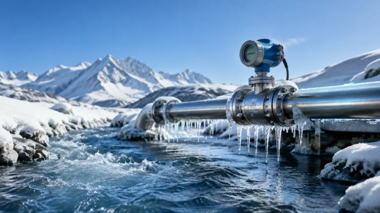
Differential Pressure Level Transmitter
Differential Pressure Level Transmitter
In the landscape of industrial automation, the differential pressure level transmitter remains one of the most versatile and widely utilized instruments for liquid level measurement. By leveraging the fundamental principles of fluid mechanics, these devices provide reliable data in environments ranging from simple water storage to complex chemical reactors. This guide explores the technical foundations, application configurations, and selection criteria essential for engineers and procurement professionals seeking to implement robust level measurement solutions.
Understanding the Measurement Principle
The operation of a differential pressure level transmitter is based on the relationship between the hydrostatic pressure exerted by a liquid column and its height. According to Pascal’s Law, the pressure at the base of a liquid column is directly proportional to the height of the liquid and its specific gravity.
The mathematical formula governing this principle is:
P = h × ρ × g
Where:
* P is the hydrostatic pressure (Pascals or bar).
* h is the height of the liquid (meters).
* ρ (rho) is the density of the liquid (kg/m³).
* g is the acceleration due to gravity (approximately 9.81 m/s²).
A differential pressure level transmitter measures the difference between two pressure points: the high-pressure side (typically at the bottom of the vessel) and the low-pressure side (typically at the top or open to the atmosphere). In a level measurement application, the transmitter converts this pressure difference into an electrical signal, such as 4-20mA or a digital HART protocol, representing the percentage of the tank's volume or height.
For a comprehensive overview of available instrumentation and technical specifications, professionals can refer to the Main Page of Welk's product catalog.
Open Tank vs. Closed Tank Applications
The configuration of a differential pressure level transmitter depends significantly on whether the vessel is vented to the atmosphere or pressurized.
Open (Vented) Tanks
In an open tank, the liquid surface is exposed to atmospheric pressure. To measure the level, the high-pressure side of the transmitter is connected to the bottom of the tank, while the low-pressure side is vented to the atmosphere. Since the atmospheric pressure acts equally on the liquid surface and the low-pressure side of the transmitter, the two cancel each other out, leaving only the hydrostatic pressure of the liquid column to be measured.
Closed (Pressurized) Tanks
In closed vessels, the space above the liquid is often occupied by pressurized gas or vapor. This internal pressure adds to the hydrostatic pressure at the bottom. To ensure the transmitter only measures the liquid level, the low-pressure side must be connected to the top of the vessel. This configuration allows the transmitter to subtract the vessel's internal pressure from the total pressure at the bottom.
There are two primary methods for connecting the low-pressure side in closed tanks:
1. Dry Leg: Used when the gas above the liquid does not condense at ambient temperatures. The pipe (leg) remains filled with gas.
2. Wet Leg: Used when the vapor above the liquid is likely to condense (e.g., steam). The low-pressure leg is intentionally filled with a reference liquid (often the process fluid or a stable glycol mixture) to provide a constant head pressure that the transmitter can account for through calibration.
Selection Criteria for Industrial Applications
Choosing the correct differential pressure level transmitter requires a detailed analysis of the process conditions. Failure to account for fluid characteristics or vessel geometry can lead to significant measurement errors.
1. Process Fluid Compatibility
The wetted parts of the transmitter, including the diaphragms and process flanges, must be resistant to corrosion. While 316L stainless steel is standard, aggressive chemicals may require Hastelloy C, Monel, or Tantalum coatings. Welk provides a range of material options to suit diverse industrial environments.
2. Pressure and Temperature Ratings
The transmitter must withstand both the static pressure of the vessel and the maximum possible process temperature. For high-temperature applications (exceeding 120°C), remote seals with capillary tubes are often used to isolate the transmitter electronics from the heat.
3. Measurement Range (Span)
The transmitter must be calibrated to the specific "span" of the tank. This involves defining the 4mA point (Zero) and the 20mA point (Full Scale). Engineers must calculate Zero Suppression if the transmitter is mounted below the tank bottom, or Zero Elevation if a wet leg is used.
4. Accuracy and Stability
In fiscal metering or high-precision chemical dosing, high-accuracy transmitters (0.075% or 0.04% of span) are required. For general monitoring in water treatment, standard accuracy models are more cost-effective.
| Feature | Differential Pressure (DP) | Radar (Non-Contact) | Ultrasonic |
| :— | :— | :— | :— |
| Measurement Principle | Hydrostatic Head | Electromagnetic Waves | Sound Waves |
| Ideal Application | Closed/Pressurized Tanks | Corrosive/Foaming Liquids | Open Channels/Water |
| Sensitivity to Density | High | None | Low |
| Installation | Bottom/Side Flange | Top Mount | Top Mount |
| Relative Cost | Moderate | High | Low/Moderate |
| Maintenance | Impulse line cleaning | Minimal | Minimal |
Installation and Maintenance Best Practices
Correct installation is paramount for the longevity and accuracy of a differential pressure level transmitter. Engineers should adhere to the following guidelines:
* Impulse Line Slope: To prevent gas bubbles from being trapped in liquid lines (or liquid from trapping in gas lines), impulse piping should have a slope of at least 1:12 (approx. 8%).
* Manifold Valves: Always install a 3-valve or 5-valve manifold. This allows the transmitter to be isolated, vented, or equalized for zero-point calibration without shutting down the process.
* Remote Seals: When using capillary systems, ensure the capillaries are shielded from direct sunlight or extreme cold, as temperature fluctuations can cause the fill fluid to expand or contract, leading to "temperature drift" in the readings.
* Vibration Isolation: In applications involving heavy pumps or agitators, mount the transmitter on a separate 2-inch pipe stand rather than directly on the vibrating vessel to protect the sensitive electronics.

Limitations and Potential Risks
While the differential pressure level transmitter is a workhorse of the industry, it is not without limitations. The most critical factor is liquid density. Because the measurement is based on weight (pressure), any change in the liquid's density—caused by temperature fluctuations or changes in chemical concentration—will result in a level error. If the density decreases, the transmitter will report a lower level than actually exists.
Furthermore, impulse lines are prone to clogging if the process fluid contains solids or is prone to crystallization. In such cases, a flush-diaphragm transmitter or a remote seal system is recommended to keep the process fluid out of the narrow impulse piping.
Frequently Asked Questions (FAQs)
Q: How does temperature affect a differential pressure level transmitter?
A: Temperature affects measurement in two ways. First, it changes the density of the process fluid, which alters the hydrostatic pressure for a given height. Second, extreme temperatures can affect the transmitter’s internal sensor. Using remote seals with capillaries can mitigate the latter, but density compensation via a PLC may be needed for the former.
Q: What is the difference between a pressure transmitter and a differential pressure transmitter?
A: A standard pressure transmitter has one process connection and measures pressure relative to the atmosphere (gauge pressure). A differential pressure transmitter has two connections (High and Low) and measures the difference between them, which is essential for level measurement in pressurized tanks.
Q: Can I use a DP transmitter for liquids with suspended solids?
A: Yes, but it is highly recommended to use a remote seal with a flush diaphragm. Standard impulse lines will likely clog, leading to erratic readings and high maintenance costs.
Q: What is Zero Suppression?
A: Zero suppression is used when the transmitter is mounted at a level lower than the minimum liquid level (the 0% mark). The transmitter must "suppress" the extra pressure exerted by the liquid in the piping between the tank and the transmitter so that 4mA still corresponds to the bottom of the tank.
Conclusion
The differential pressure level transmitter remains a cornerstone of industrial process control due to its reliability and well-understood operating principles. By carefully considering the vessel type, fluid properties, and installation environment, engineers can ensure accurate and long-term performance. For those evaluating specific models for water treatment, oil and gas, or chemical automation, consulting the technical documentation on the Main Page of an established manufacturer like Welk is the recommended next step to ensure the selected hardware meets all safety and performance standards.