Differential Pressure Transducers
Differential Pressure Transducers
Differential pressure transducers are fundamental components in industrial process control, serving as the primary mechanism for measuring the difference in pressure between two points in a system. Unlike standard pressure sensors that measure against a vacuum or atmospheric reference, differential pressure transducers utilize two process ports to determine the delta between a high-pressure side and a low-pressure side. This capability makes them indispensable for monitoring fluid flow, liquid levels in pressurized vessels, and the integrity of filtration systems.
In the context of industrial automation, these instruments provide the critical data necessary for maintaining safety, efficiency, and product quality. Whether applied in water treatment, chemical processing, or oil and gas production, understanding the underlying physics and selection criteria for these devices is essential for any engineering project.
Measurement Principles of Differential Pressure Transducers
The operation of differential pressure transducers is rooted in the mechanical displacement of a sensing element, typically a diaphragm, positioned between two pressure chambers. When pressure is applied to both sides, the diaphragm moves toward the side with lower pressure. This physical displacement is then converted into an electrical signal.
Hydrostatic Level Measurement
In level measurement applications, particularly within closed or pressurized tanks, differential pressure is used to calculate the height of a liquid. The high-pressure (HP) side of the transducer is connected to the bottom of the tank, while the low-pressure (LP) side is connected to the gas space at the top.
The relationship is defined by the formula:
$$H = \frac{\Delta P}{\rho \cdot g}$$
Where:
* H is the liquid height (meters).
* ΔP is the differential pressure measured (Pascals or bar).
* ρ (rho) is the density of the liquid (kg/m³).
* g is the acceleration due to gravity (approximately 9.81 m/s²).
By subtracting the head pressure of the gas or vapor space (measured at the LP port) from the total pressure at the bottom (measured at the HP port), the transducer isolates the pressure exerted solely by the liquid column.
Flow Measurement via Primary Elements
Differential pressure transducers are also the standard for flow measurement when paired with primary elements like orifice plates, Venturi tubes, or Pitot tubes. According to Bernoulli’s principle, as a fluid passes through a restriction, its velocity increases and its pressure decreases. The transducer measures the pressure drop across this restriction. The flow rate is proportional to the square root of the differential pressure, allowing for precise volumetric or mass flow calculations.
Key Evaluation Criteria for Selection
Selecting the correct differential pressure transducer requires a thorough analysis of the process environment and the specific requirements of the application. Engineers must look beyond basic pressure ranges to ensure long-term reliability.
1. Sensor Technology
Different sensing technologies offer varying levels of accuracy and stability:
* Piezoresistive: Utilizes strain gauges bonded to a diaphragm. These are cost-effective and highly sensitive but can be susceptible to temperature fluctuations.
* Capacitive: Measures the change in capacitance as a diaphragm moves between two fixed plates. These are known for high accuracy and excellent long-term stability.
* Silicon Resonant: Uses the change in resonant frequency of a silicon crystal. These offer the highest precision and are often used in custody transfer applications.
2. Wetted Materials and Chemical Compatibility
The diaphragm and process flanges must be compatible with the media. While 316L stainless steel is standard, corrosive applications in the chemical industry may require exotic materials such as Hastelloy C-276, Monel, or Tantalum. For food and beverage or pharmaceutical applications, hygienic seals and specialized filling fluids (such as food-grade oil) are required.
3. Static Pressure Rating
It is vital to distinguish between the differential pressure range and the maximum static (working) pressure. A transducer might measure a small differential of 500 mbar, but it must be able to withstand a static line pressure of 100 bar without mechanical failure or significant zero-shift.
4. Turndown Ratio and Accuracy
The turndown ratio defines the range over which the instrument can maintain its specified accuracy. A high turndown ratio (e.g., 100:1) allows a single device to be calibrated for various ranges, providing flexibility in inventory management and process scaling.
Practical Selection Table
| Feature | Piezoresistive Transducers | Capacitive Transducers | Silicon Resonant Transducers |
| :— | :— | :— | :— |
| Typical Accuracy | 0.1% to 0.5% FS | 0.05% to 0.1% FS | 0.025% to 0.05% FS |
| Stability | Moderate | High | Very High |
| Cost | Low to Mid | Mid to High | High |
| Overpressure Resistance | Moderate | High | Excellent |
| Best Use Case | General industrial automation | Process level & flow control | High-precision custody transfer |
Installation Considerations and Best Practices
The performance of differential pressure transducers is heavily dependent on the quality of the installation. Even the most accurate sensor will provide erroneous data if the impulse lines or mounting orientation are incorrect.
Impulse Piping and Manifolds
Impulse lines connect the process pipe or tank to the transducer. These lines should be as short as possible to minimize lag and potential for clogging. A slope of at least 1:12 is recommended—sloping up for gas applications (to allow condensate to drain back) and sloping down for liquid applications (to allow gas bubbles to escape).
A 3-valve or 5-valve manifold is essential. These manifolds allow for the isolation of the transducer from the process, the equalization of pressure across the diaphragm during zero-calibration, and the venting of the system without shutting down the process line.
Orientation and Mounting
Transducers should be mounted in a vibration-free location. If the device is mounted at a different elevation than the process tapping points, the weight of the liquid column in the impulse lines (the "wet leg") must be accounted for during calibration. This is known as zero-suppression or zero-elevation.
Environmental Protection
In outdoor installations, transducers should be protected from direct sunlight and extreme temperature swings using sunshades or heated enclosures. Temperature changes can cause the fill fluid inside the sensor to expand or contract, leading to "temperature drift" in the readings.
For comprehensive technical specifications and to explore various sensor configurations, engineers can visit the Main Page of the Welk product catalog.
Common Risks and Limitations
While differential pressure transducers are versatile, they are not without limitations. Recognizing these risks early in the design phase can prevent costly downtime.
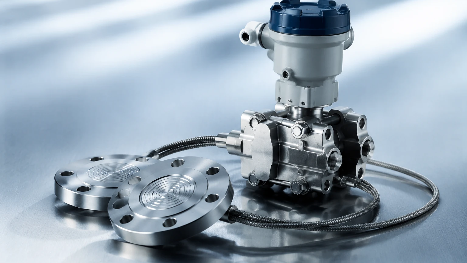
* Clogging of Impulse Lines: In applications involving slurries or viscous fluids, impulse lines can become blocked. This is often mitigated by using remote diaphragm seals, which replace the impulse lines with a capillary system filled with transmission fluid.
* Hydrogen Permeation: In high-pressure hydrogen service, hydrogen atoms can permeate through metal diaphragms, forming bubbles in the fill fluid and causing sensor failure. Gold-plated diaphragms are typically required for these environments.
* Overpressure Events: If one side of the transducer is suddenly vented while the other remains under high pressure, the diaphragm can be permanently deformed. High-quality transducers include internal overpressure protection mechanisms to prevent this.
* Density Variations: Since DP level measurement relies on the density of the fluid, any change in temperature or concentration that alters the density will result in measurement errors unless compensation is applied via a secondary temperature sensor.
Frequently Asked Questions (FAQ)
Q: Can differential pressure transducers be used for vacuum applications?
A: Yes, but the sensor must be specifically rated for vacuum service. Standard fill fluids may boil or outgas under deep vacuum, which can damage the diaphragm or cause significant drift.
Q: What is the difference between a pressure transmitter and a pressure transducer?
A: In industrial terminology, a transducer typically refers to the sensing element that converts pressure to a low-level electrical signal (like mV), while a transmitter includes signal conditioning circuitry to provide a standardized output, such as 4-20mA, HART, or Foundation Fieldbus.
Q: How often should DP transducers be calibrated?
A: Calibration frequency depends on the criticality of the process and the stability of the sensor technology. Most industrial standards recommend an annual check, though high-stability capacitive or resonant sensors may extend this interval to 2-5 years.
Q: What is a "remote seal" and when should I use it?
A: A remote seal uses a flexible diaphragm and a capillary tube to isolate the transducer from the process media. It is used when the media is extremely hot, corrosive, viscous, or prone to solidification in impulse lines.
Conclusion for Project Planning
Before finalizing a specification for differential pressure transducers, project teams should confirm the following data points:
1. The exact chemical composition of the process fluid to ensure material compatibility.
2. The maximum static pressure the system will reach during start-up or cleaning cycles (CIP/SIP).
3. The ambient and process temperature ranges, as these dictate the need for specialized fill fluids or remote seals.
4. The required communication protocol (e.g., 4-20mA HART, Modbus, or Profibus) for integration into the existing PLC or DCS.
By addressing these factors and following established installation guidelines, differential pressure transducers provide a reliable and accurate solution for the most demanding industrial measurement challenges.