Displacer Level Sensor
Displacer Level Sensor
In the field of industrial process control, the displacer level sensor remains a cornerstone technology for high-pressure and high-temperature applications. Unlike simple float switches, a displacer level sensor operates on the principle of buoyancy to provide continuous level or interface measurement. This guide provides a technical overview of its measurement principles, selection criteria, and practical installation considerations for engineering professionals.
Measurement Principle: Archimedes’ Law in Practice
The fundamental operation of a displacer level sensor is rooted in Archimedes' Principle, which states that a body immersed in a fluid is buoyed up by a force equal to the weight of the fluid displaced by the body.
Displacement vs. Flotation
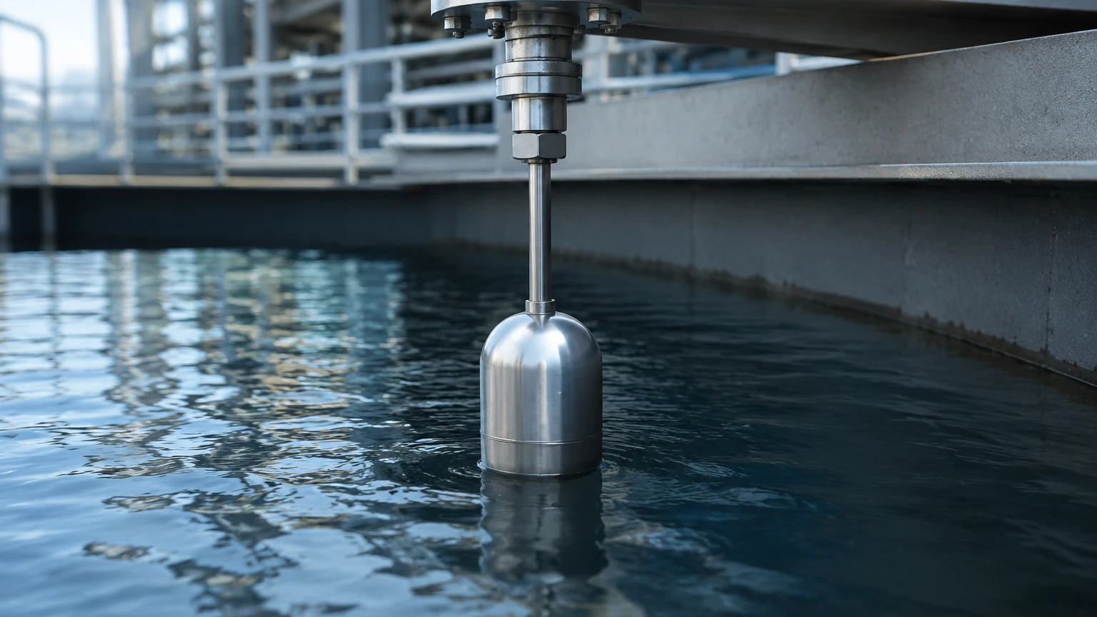
It is critical to distinguish between a float and a displacer. A float is designed to be lighter than the process liquid, allowing it to ride on the surface. In contrast, a displacer is intentionally designed to be heavier than the liquid. It remains partially or fully submerged throughout its measurement range.
As the liquid level rises, the displacer experiences an increasing buoyant force. This force reduces the "apparent weight" of the displacer. The sensor mechanism—typically a torque tube or a spring-balanced system—detects this change in weight. The relationship is linear: as the level increases, the apparent weight decreases. The transmitter then converts this mechanical change into a standard 4-20mA or digital signal.
The Torque Tube Mechanism
Most heavy-duty industrial displacer sensors utilize a torque tube. The displacer is suspended from a rod attached to the end of a tube. As the buoyant force changes, it exerts a twisting force (torque) on the tube. The degree of twist is proportional to the liquid level. Because the torque tube is a sealed mechanical component, it provides an excellent pressure barrier, isolating the electronic components from the process environment.
Interface Measurement Capabilities
One of the primary reasons engineers specify a displacer level sensor is its ability to measure the interface between two immiscible liquids, such as oil and water.
In interface applications, the displacer is always fully submerged. The sensor detects the change in buoyant force caused by the shifting ratio of the two liquids. For this to work effectively, there must be a significant density difference (typically at least 0.1 g/cm³) between the upper and lower liquids. The total buoyant force is the sum of the forces exerted by both liquids. As the heavier liquid (e.g., water) displaces the lighter liquid (e.g., oil) around the submerged displacer, the total buoyant force increases, signaling a rise in the interface level.
Key Evaluation Criteria for Selection
When selecting a displacer level sensor for a project, several technical parameters must be confirmed to ensure accuracy and long-term reliability.
1. Process Fluid Density (Specific Gravity)
Since the measurement is weight-based, the accuracy is entirely dependent on the density of the process fluid. If the density changes due to temperature fluctuations or process variations, the sensor will report an error. High-end transmitters often include temperature compensation to mitigate this risk.
2. Pressure and Temperature Ratings
Displacers excel in extreme environments where non-contact sensors might fail. They are commonly available for pressures up to 400 bar (approx. 5,800 psi) and temperatures ranging from -196°C to +450°C (-320°F to +840°F). The material of the torque tube and displacer must be compatible with these extremes.
3. Material Compatibility
The displacer, suspension rod, and chamber (cage) are in constant contact with the process media. Standard materials include 316 Stainless Steel, but for corrosive chemical applications, materials like Monel, Hastelloy C, or Inconel are often required.
4. Measurement Range
The length of the displacer determines the measurement span. Standard lengths range from 355 mm (14 inches) to over 3 meters (120 inches). For very long spans, hydrostatic or radar technologies may be more cost-effective, but the displacer remains superior for high-pressure narrow-span interface control.
Technical Selection Table
| Feature | Specification Range | Engineering Note |
| :— | :— | :— |
| Standard Accuracy | ±0.2% to ±0.5% of span | Highly dependent on density stability. |
| Pressure Rating | Vacuum to 425 bar (6160 psi) | Suitable for high-pressure separators. |
| Temperature Range | -196°C to +450°C | Excellent for cryogenic or steam service. |
| Min. Density Diff. | 0.1 g/cm³ | Required for reliable interface measurement. |
| Output Signals | 4-20mA, HART, Foundation Fieldbus | Compatible with modern DCS/PLC systems. |
| Mounting | Top or Side (External Cage) | External cages allow for isolation valves. |
Installation Considerations
Proper installation is vital for the performance of a displacer level sensor. Because the sensor relies on mechanical movement, any friction or misalignment will result in measurement errors.
* External Chambers (Cages): It is common practice to install the displacer in an external chamber mounted to the side of the vessel. This configuration allows for the installation of isolation valves, enabling maintenance or calibration without shutting down the entire process.
* Stillwells: If the sensor is mounted directly inside a vessel with high turbulence or agitation, a stillwell (a vertical pipe) must be used to protect the displacer from lateral forces that could bend the suspension rod or cause erratic readings.
* Vertical Alignment: The displacer must hang perfectly vertical. Any contact between the displacer and the chamber wall will create friction, leading to "stiction" and non-linear output.
* Venting and Draining: External chambers should be equipped with vent and drain valves to allow for safe commissioning and the removal of accumulated solids or gas pockets.
Common Risks and Limitations
While robust, the displacer level sensor is not a universal solution. Engineers should be aware of the following limitations:
1. Build-up and Coating: If the process fluid is prone to scaling or heavy coating, the weight of the displacer will change over time, leading to a zero-shift error. In such cases, non-contact radar or ultrasonic sensors may be preferable. For more information on alternative technologies, you can Review product options and application support on our Main Page.
2. Turbulence: High-velocity fluid entry near the displacer can cause it to swing, potentially damaging the torque tube or suspension assembly.
3. Density Fluctuations: In processes where the fluid composition changes frequently, the displacer will require constant recalibration. If the density varies by more than 5%, the resulting error may exceed process tolerances.
Maintenance and Calibration
Calibration of a displacer level sensor can be performed using two primary methods:
* Wet Calibration: The chamber is filled with the actual process fluid (or a surrogate with known density) to specific levels (0%, 50%, 100%). This is the most accurate method but can be time-consuming.
* Dry Calibration (Weight Method): Since the buoyant force is known for a given level, precisely calculated weights can be hung from the torque tube arm to simulate the buoyant force. This is often used during commissioning when filling the vessel is not practical.
Routine maintenance should include inspecting the torque tube for signs of fatigue or corrosion and ensuring the displacer is free of debris. In high-vibration environments, the linkage between the torque tube and the transmitter should be checked for wear.
Frequently Asked Questions (FAQs)
Q: Can a displacer level sensor be used for liquids with foam?
A: Yes. Because the displacer responds to the weight of the displaced liquid, it is generally unaffected by light foam on the surface, which has negligible density. This gives it an advantage over ultrasonic or some radar sensors in foaming applications.
Q: What happens if the displacer falls off the hook?
A: The transmitter will detect a sudden increase in weight (the full weight of the displacer is gone, leaving only the rod). Most modern smart transmitters will trigger a diagnostic alarm indicating a "displacer loss" or hardware failure.
Q: Is it possible to use a displacer for solids or slurries?
A: It is generally not recommended. Solids can settle in the bottom of the chamber, pinning the displacer or changing the effective volume of the chamber. For slurries, a flush-diaphragm hydrostatic transmitter or a non-contact radar is usually a better choice.
Q: How does temperature affect the torque tube?
A: As temperature increases, the elastic modulus of the torque tube material changes slightly. High-quality displacer level sensors use materials with very stable temperature coefficients and include electronic compensation to maintain accuracy across the operating range.
Conclusion for Project Planning
The displacer level sensor remains a reliable choice for critical process loops, particularly in the oil and gas, petrochemical, and power industries. Its mechanical simplicity and ability to withstand extreme pressures make it indispensable for high-integrity applications.
Before proceeding with a purchase, project teams should confirm the exact specific gravity of the fluids involved at operating temperatures and determine if an external cage is required for maintenance access. For a comprehensive range of industrial measurement solutions including radar, ultrasonic, and hydrostatic options, visit the Main Page to explore technical specifications and support for your specific application.