Dissolved Oxygen Measurement
Dissolved Oxygen Measurement
Dissolved oxygen (DO) measurement is a critical parameter in various industrial, environmental, and process control applications. It refers to the amount of gaseous oxygen (O₂) dissolved in a liquid, typically water. In industrial contexts, maintaining precise DO levels is essential for biological wastewater treatment, the prevention of corrosion in high-pressure boilers, and the optimization of chemical reactions.
As a professional manufacturer of industrial measurement instruments, Welk provides high-performance solutions for process automation. While level measurement remains a core focus, the integration of water quality parameters like dissolved oxygen is vital for comprehensive plant management. Engineers seeking reliable instrumentation often consult the Main Page to review product options and application support for complex industrial environments.
Understanding Dissolved Oxygen Principles
Before selecting a measurement technology, it is necessary to understand the physics of how oxygen dissolves in a liquid and how sensors detect it. The concentration of dissolved oxygen is governed by Henry's Law, which states that the amount of dissolved gas in a liquid is proportional to its partial pressure in the gas phase above the liquid. Factors such as temperature, atmospheric pressure, and salinity significantly influence DO solubility.
There are two primary sensing technologies used in modern industrial dissolved oxygen measurement: electrochemical and optical.
1. Electrochemical Measurement Principles
Electrochemical sensors, often referred to as Clark cells, have been the industry standard for decades. They operate by reducing oxygen at a cathode, which generates an electrical current proportional to the oxygen concentration.
* Polarographic Sensors: These sensors utilize a gold or platinum cathode and a silver anode immersed in a potassium chloride (KCl) electrolyte. A constant polarizing voltage is applied to the electrodes. When oxygen molecules diffuse through a gas-permeable membrane, they are reduced at the cathode, creating a current flow. These sensors typically require a "warm-up" period of 15 to 60 minutes to stabilize the polarization.
* Galvanic Sensors: In a galvanic setup, the electrodes are made of dissimilar metals (e.g., a lead anode and a gold cathode). The difference in electrochemical potential between these metals is sufficient to drive the reaction spontaneously, meaning no external polarizing voltage is required. Consequently, galvanic sensors offer an "instant-on" capability.
2. Optical Measurement Principles (Luminescence)
Optical dissolved oxygen (LDO) sensors represent a more recent advancement in instrumentation. They operate based on the principle of "dynamic luminescence quenching."
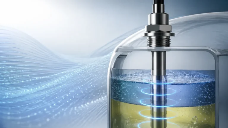
The sensor head contains a sensing element coated with a luminescent material (luminophore). An LED inside the sensor shines blue light on the luminophore, exciting the molecules and causing them to emit red light as they return to a lower energy state. If oxygen molecules are present, they collide with the excited luminophore and "quench" the luminescence. The sensor measures either the intensity of the emitted red light or the time it takes for the luminescence to decay. The more oxygen present, the shorter the decay time and the lower the intensity.
Key Selection Criteria for Industrial DO Sensors
Choosing the right sensor requires an evaluation of the process environment and maintenance capabilities. The following criteria should guide the selection process:
1. Response Time: Electrochemical sensors generally have a faster initial response to rapid changes in DO, but optical sensors are more stable over long periods.
2. Flow Requirements: Electrochemical sensors consume oxygen during the measurement process. Therefore, a minimum flow rate (typically 0.3 m/s) across the membrane is required to ensure a fresh sample is always present. Optical sensors do not consume oxygen and can be used in stagnant water.
3. Maintenance Frequency: Electrochemical sensors require periodic electrolyte replacement and membrane changes. Optical sensors only require the replacement of the sensor cap, typically once every 12 to 24 months.
4. Chemical Interference: Electrochemical sensors are susceptible to interference from gases like hydrogen sulfide (H₂S), which can poison the electrodes. Optical sensors are generally immune to such chemical interferences.
Comparison Table: Technology Selection
| Feature | Polarographic (Electrochemical) | Galvanic (Electrochemical) | Optical (Luminescence) |
| :— | :— | :— | :— |
| Warm-up Time | 15–60 minutes | None | None |
| Oxygen Consumption | Yes | Yes | No |
| Flow Dependence | High (requires movement) | High (requires movement) | None |
| Maintenance | High (Electrolyte/Membrane) | High (Electrolyte/Membrane) | Low (Sensor Cap) |
| H2S Sensitivity | High | High | None |
| Initial Cost | Moderate | Moderate | High |
| Long-term Stability | Moderate | Moderate | Excellent |
Installation Best Practices
Proper installation is paramount to achieving accurate dissolved oxygen measurement. Incorrect placement can lead to air entrapment or stagnant zones that do not represent the bulk process fluid.
Sensor Placement
* Avoid Air Pockets: In pipe installations, sensors should be installed on the side of the pipe rather than the top to avoid air bubbles, and not at the bottom to avoid sediment buildup.
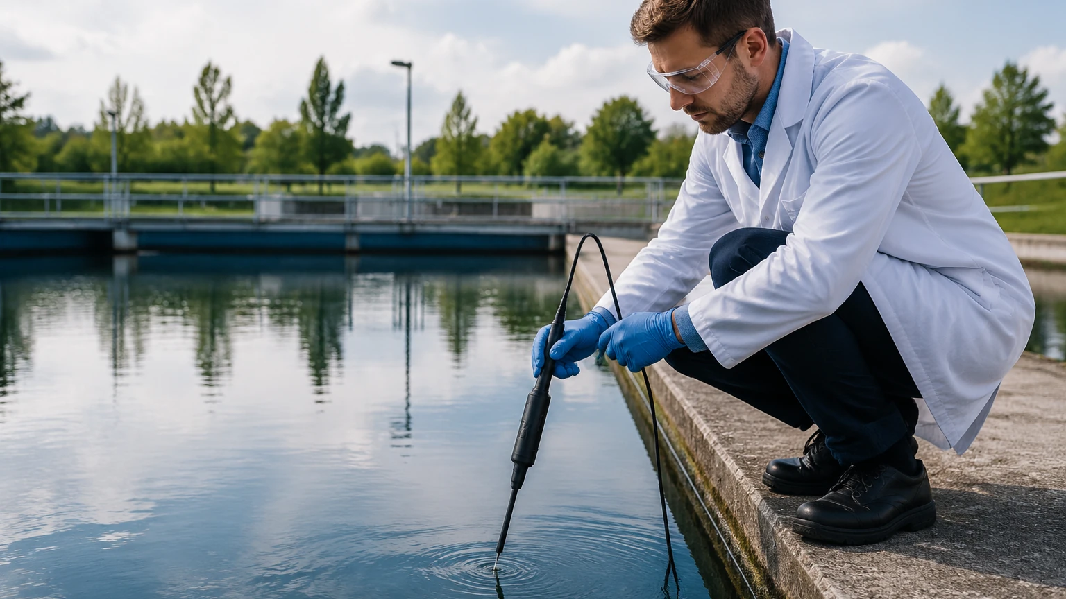
* Submersion Depth: For open tank applications, such as aeration basins in wastewater treatment, the sensor should be submerged at a depth that avoids surface turbulence (which can artificially inflate DO readings) but remains within the active mixing zone.
* Orientation: Most sensors should be installed at an angle (typically 15° to 45° from vertical) to prevent air bubbles from clinging to the sensing membrane or optical window.
Integration with Control Systems
Modern industrial DO transmitters provide various output options for integration with PLC or SCADA systems. Standard outputs include 4-20 mA analog signals, often with HART protocol, or digital communication via RS485 (Modbus RTU). When designing a system, ensure the transmitter is compatible with the existing automation infrastructure found on the Main Page.
Limitations and Environmental Considerations
While DO sensors are robust, certain environmental factors can impair performance:
* Temperature Compensation: The solubility of oxygen is highly temperature-dependent. As temperature increases, solubility decreases. Most industrial sensors include an internal thermistor (PT100 or PT1000) to provide automatic temperature compensation.
* Salinity Correction: In applications involving seawater or brackish water, dissolved salts reduce the solubility of oxygen (the "salting-out" effect). If the salinity is constant, a correction factor can be programmed into the transmitter. If salinity fluctuates, a separate conductivity sensor may be required for real-time compensation.
* Pressure Effects: Changes in barometric pressure or process pressure affect the partial pressure of oxygen. For high-accuracy applications, pressure compensation is necessary, especially if the sensor is calibrated at a different altitude than the installation site.
Maintenance and Calibration Procedures
To ensure long-term reliability, a structured maintenance schedule is required.
Calibration Methods
1. Air Calibration (Water-Saturated Air): The most common and easiest method. The sensor is held in air just above the water surface. Since the concentration of oxygen in the air is constant (approximately 20.95%), the sensor can be calibrated to this known value.
2. Winkler Titration: A chemical method used to verify sensor accuracy against a laboratory standard. This is often used for regulatory compliance in wastewater treatment.
3. Zero-Point Calibration: Required for low-level DO applications (e.g., boiler feed water). The sensor is placed in an oxygen-free environment, such as water containing excess sodium sulfite ($Na_2SO_3$) or pure nitrogen gas.
Cleaning
Biofouling is the most common cause of drift in DO measurement. In wastewater applications, sensors should be cleaned weekly or equipped with automated cleaning systems (e.g., compressed air blasts or mechanical wipers) to prevent the growth of biofilm on the sensing surface.
Frequently Asked Questions (FAQ)
Q: How often should I calibrate my DO sensor?
A: For optical sensors in clean water, calibration every 3–6 months is often sufficient. In wastewater or high-fouling environments, electrochemical sensors may require weekly calibration, while optical sensors may need it monthly.
Q: Can I use a DO sensor in non-aqueous liquids?
A: Most DO sensors are designed for water-based applications. Usage in oils or solvents requires specialized materials for the membranes and seals to prevent chemical degradation.
Q: What is the difference between mg/L and % saturation?
A: mg/L (or ppm) measures the actual mass of oxygen dissolved in a liter of water. % Saturation measures the amount of oxygen relative to the maximum amount the water could hold at that specific temperature, pressure, and salinity. Most industrial transmitters can toggle between these units.
Q: Why is my DO reading higher than expected in an aeration tank?
A: This is often caused by air bubbles directly striking the sensor membrane. Repositioning the sensor or using a baffle can help ensure you are measuring dissolved oxygen, not entrained air bubbles.
Conclusion
Effective dissolved oxygen measurement is a cornerstone of modern process engineering. Whether utilizing the proven reliability of electrochemical cells or the low-maintenance benefits of optical technology, understanding the underlying principles and environmental constraints is essential. By following rigorous installation and maintenance protocols, operators can ensure process stability and energy efficiency. For further technical specifications and to explore a wider range of industrial measurement solutions, engineers are encouraged to visit the Main Page for expert guidance and product selection.