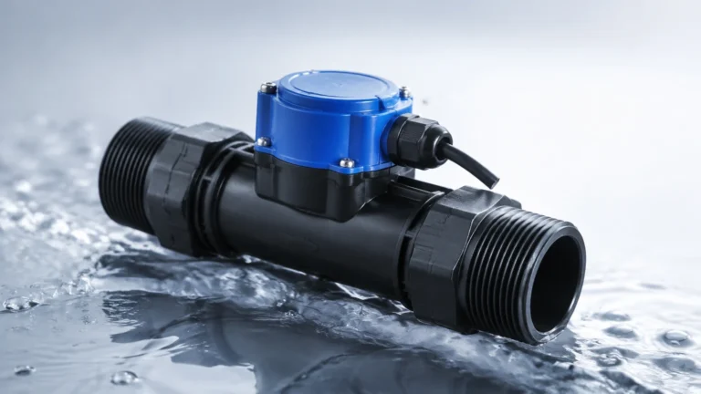
Dp Transmitter
Dp Transmitter
In the landscape of industrial process control, the differential pressure transmitter, commonly referred to as a dp transmitter, remains one of the most versatile and widely utilized instruments. Whether measuring the flow of steam, the level of a liquid in a pressurized vessel, or the pressure drop across a filter, these devices provide critical data for automation and safety. For engineers and technicians, understanding the underlying physics, application nuances, and installation requirements is essential for ensuring long-term reliability and accuracy.
As a professional manufacturer of industrial level measurement instruments, Welk provides a comprehensive range of solutions, including radar, ultrasonic, and hydrostatic sensors. However, the dp transmitter remains a cornerstone of our portfolio due to its adaptability in complex process environments. For a full overview of our technical capabilities, you may visit our Main Page.
Understanding the Operating Principles of DP Transmitters
The fundamental operation of a dp transmitter is based on the detection of a pressure difference between two distinct points. The device typically features two process connections: a high-pressure (HP) side and a low-pressure (LP) side. The internal sensing element, often a piezoresistive silicon sensor or a capacitive cell, detects the mechanical displacement caused by the pressure imbalance and converts it into an electrical signal, usually a 4-20mA HART or digital output.
Hydrostatic Level Measurement
In level measurement applications, the dp transmitter utilizes the principle of hydrostatic pressure. According to Pascal’s Law, the pressure exerted by a liquid column is proportional to its height and density. The formula is expressed as:
P = ρ × g × h
Where:
* P is the hydrostatic pressure (Pa).
* ρ (rho) is the density of the fluid (kg/m³).
* g is the acceleration due to gravity (approximately 9.81 m/s²).
* h is the height of the liquid (m).
In an open tank, the LP side of the transmitter is vented to the atmosphere, while the HP side is connected to the bottom of the tank. In a pressurized (closed) tank, the LP side is connected to the vapor space at the top of the vessel to cancel out the effect of the internal tank pressure, leaving only the pressure exerted by the liquid column to be measured.
Flow Measurement Principles
When used for flow, the dp transmitter is paired with a primary flow element, such as an orifice plate, Venturi tube, or Pitot tube. These elements create a deliberate restriction in the pipe, causing a pressure drop. According to Bernoulli’s Equation, the square root of this pressure difference is proportional to the flow rate. This allows the transmitter to calculate volumetric or mass flow based on the detected differential pressure.
Key Applications in Industrial Environments
1. Pressurized Vessel Level Control
In industries like oil and gas or chemical processing, liquids are often stored under high pressure or blanketed with nitrogen. A standard hydrostatic probe cannot distinguish between the liquid head and the gas pressure. The dp transmitter excels here by subtracting the gas pressure (LP side) from the total pressure at the bottom (HP side), providing an accurate liquid level reading regardless of fluctuations in tank pressure.
2. Interface Level Measurement
When two immiscible liquids with different densities (such as oil and water) are present in the same tank, a dp transmitter can be calibrated to detect the interface level. This requires the vessel to be full or for the transmitter to be used in conjunction with other sensors to account for total volume.
3. Filter and Heat Exchanger Monitoring
By measuring the pressure drop across a filter or heat exchanger, a dp transmitter can signal when a component is becoming clogged or fouled. An increase in differential pressure beyond a set threshold triggers maintenance alerts, preventing equipment damage and optimizing energy efficiency.
Key Selection Criteria for Industrial DP Transmitters
Choosing the right dp transmitter requires a detailed analysis of the process conditions. The following table outlines the primary factors that must be evaluated during the procurement phase.
| Criteria | Description | Engineering Impact |
| :— | :— | :— |
| Pressure Range | The maximum and minimum differential pressure expected. | Determines the sensor diaphragm thickness and sensitivity. |
| Static Pressure | The maximum working pressure the vessel or pipe will endure. | The transmitter body must withstand the total system pressure without leaking or failing. |
| Wetted Materials | Materials in contact with the process fluid (e.g., 316L SS, Hastelloy, Monel). | Prevents chemical corrosion and ensures long-term integrity. |
| Diaphragm Seals | Use of remote seals with capillaries. | Necessary for high-temperature, corrosive, or highly viscous fluids that shouldn't enter the transmitter body. |
| Accuracy Class | Standard (0.075%) vs. High Accuracy (0.04%). | Critical for custody transfer or high-precision chemical dosing. |
| Output Protocol | 4-20mA, HART, Profibus, or Foundation Fieldbus. | Ensures compatibility with the existing PLC/DCS control system. |
Installation Considerations and Best Practices
The performance of a dp transmitter is heavily dependent on the quality of its installation. Even the most expensive instrument will provide inaccurate data if the impulse lines or mounting positions are incorrect.
Impulse Piping Layout
Impulse lines are the small-bore pipes that connect the process to the transmitter.
* Gas Applications: The transmitter should be mounted above the process tapping points so that any condensed liquid drains back into the process line.
* Liquid and Steam Applications: The transmitter should be mounted below the tapping points to ensure the impulse lines remain filled with liquid, preventing gas bubbles from causing erratic readings.
The Use of Manifolds
A 3-valve or 5-valve manifold is an indispensable accessory. It allows the transmitter to be isolated from the process for calibration or maintenance without shutting down the entire line. The equalizing valve on the manifold is critical for zeroing the transmitter under static pressure conditions.
Remote Seals and Capillaries
In applications involving extreme temperatures (above 120°C) or hygienic requirements (food and beverage), remote seals are used. These seals use a thin diaphragm and a fill fluid (such as silicone oil) to transmit pressure through a capillary tube to the sensor. When installing these, it is vital to account for the "seal pot" effect and the head pressure exerted by the fill fluid itself, which must be compensated for during calibration (Zero Elevation or Zero Suppression).

Limitations and Environmental Factors
While highly versatile, dp transmitters have specific limitations that engineers must manage:
1. Density Sensitivity: Since the measurement is based on weight (hydrostatic head), any change in the fluid’s density—caused by temperature fluctuations or changes in chemical composition—will result in a level error. In such cases, temperature compensation or the use of a secondary density-measuring device may be required.
2. Clogging Risks: Impulse lines are susceptible to plugging if the process fluid contains solids or waxes. Regular purging or the use of large-bore diaphragm seals can mitigate this risk.
3. Ambient Temperature Effects: Extreme cold can cause the fluid in impulse lines to freeze or become highly viscous. Heat tracing and insulation are often required in outdoor installations in temperate or arctic climates.
Comparison with Alternative Level Technologies
To help engineers decide if a dp transmitter is the best choice, the following table compares it to other common technologies offered by Welk.
| Technology | Best For | Pros | Cons |
| :— | :— | :— | :— |
| DP Transmitter | Pressurized tanks, flow, filters. | Proven, versatile, handles high pressure. | Density dependent, requires impulse lines. |
| Radar (Non-contact) | Corrosive liquids, solids, high accuracy. | No contact with media, density independent. | Higher initial cost, sensitive to foam. |
| Ultrasonic | Water treatment, open channels. | Cost-effective, easy to install. | Affected by vapor, dust, and temperature gradients. |
| Magnetic Level Gauge | Visual indication, high-pressure boilers. | Robust, no power required for visual. | Limited to liquids, mechanical moving parts. |
Frequently Asked Questions (FAQ)
Q: What is the difference between Zero Elevation and Zero Suppression?
A: Zero Suppression is used when the transmitter is mounted below the bottom tapping point; the weight of the liquid in the impulse line creates a positive pressure that must be "suppressed." Zero Elevation is used when a dry leg or remote seal on the LP side creates a vacuum or negative pressure effect relative to the HP side, requiring the zero point to be "elevated."
Q: How often should a dp transmitter be calibrated?
A: While modern digital transmitters are very stable, a standard practice is to perform a calibration check every 1 to 2 years. In critical safety loops or high-fouling environments, 6-month intervals may be necessary.
Q: Can a dp transmitter measure the level of solids?
A: Generally, no. DP transmitters rely on hydrostatic pressure, which does not behave the same way in solids (powders/grains) due to internal friction and bridging. For solids, we recommend radar or ultrasonic sensors.
Q: Why is my DP reading drifting?
A: Drifting is often caused by temperature changes affecting the fill fluid in capillaries, a leak in the impulse piping, or gas bubbles trapped in a liquid-filled impulse line. Ensuring proper venting and insulation usually resolves these issues.
For technical support in selecting the appropriate instrumentation for your facility, or to view our full catalog of level and pressure solutions, please visit the Welk Main Page. Our engineering team is available to assist with custom OEM/ODM requirements and site-specific application challenges.