What Is a Flow Line
What Is a Flow Line
In the context of industrial fluid handling and process engineering, understanding the infrastructure that moves raw materials is fundamental to maintaining system integrity and operational efficiency. One of the most critical components in these systems is the flow line. While the term may appear generic, in industries such as oil and gas, chemical processing, and water treatment, it carries specific technical implications regarding the transport of fluids from a source to a processing or storage destination.
For engineers and plant operators, defining what is a flow line involves more than just identifying a pipe; it requires an understanding of how these lines interact with downstream equipment, such as separators and storage tanks, where precise level measurement becomes essential. This article explores the technical definition of flow lines, their role in industrial ecosystems, and how level measurement technologies from the Main Page of instrumentation providers ensure these systems operate safely.
Defining the Flow Line in Industrial Processes
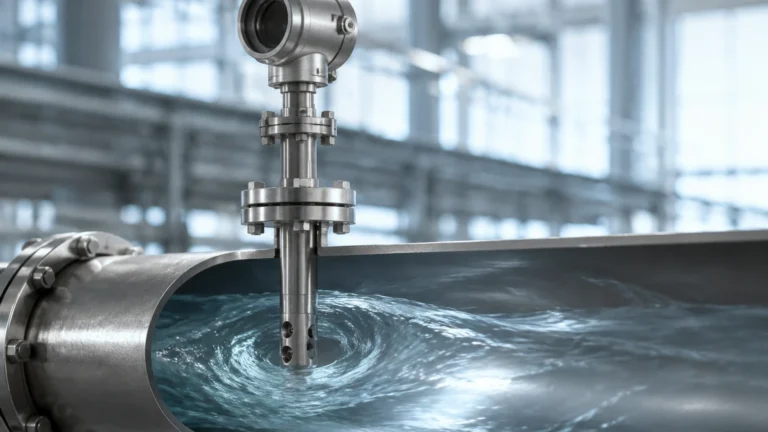
A flow line is a pipeline that connects a wellhead or a primary fluid source to a manifold, a header, a process unit, or a storage vessel. In the upstream oil and gas sector, a flow line specifically refers to the pipe that carries the full well stream—often a mixture of oil, gas, and produced water—from the individual well to a gathering station or a separator.
Unlike transmission pipelines, which transport refined or processed fluids over long distances at high pressures, flow lines are typically shorter and operate within the confines of a specific production field or industrial plant. They are the "arteries" of the initial production phase. Because the fluids within a flow line are often untreated, they can be corrosive, abrasive, or multi-phase, which necessitates robust material selection and constant monitoring of the vessels they feed.
Types of Flow Lines and Their Applications
Flow lines are categorized based on the fluid they transport and their position within the process flow. Understanding these variations is the first step in selecting the appropriate monitoring equipment.
1. Production Flow Lines
These carry the raw output from a source to the first stage of processing. In chemical plants, this might be the line from a reactor to a buffer tank. In oil fields, it is the line from the Christmas tree (wellhead) to the test separator.
2. Water Injection Lines
Used primarily in secondary recovery operations or water treatment facilities, these lines transport water to be injected into a system to maintain pressure or dispose of treated effluent.
3. Gathering Lines
When multiple flow lines from different sources meet at a single point (a manifold), the resulting larger pipe that carries the combined flow to a central processing facility is often referred to as a gathering line. These lines handle higher volumes and require sophisticated level management at the receiving terminal to prevent overfills.
The Role of Level Measurement at Flow Line Termination Points
While a flow line is a conduit for movement, its termination point—usually a tank or a separator—is where the fluid is managed. Precise level measurement at these points is critical for several reasons:
* Phase Separation: In separators fed by flow lines, level meters must distinguish between oil, water, and gas layers to ensure each is routed correctly.
* Pump Protection: If the level in a receiving tank drops too low, pumps can cavitate and sustain damage. Conversely, high levels can lead to dangerous overflows.
* Process Optimization: Monitoring the rate of level change in a vessel can provide indirect data on the flow line's performance and the source's productivity.
Measurement Principles for Level Monitoring in Flow Systems
Before recommending specific instruments, it is vital to understand the physics behind the measurement. For systems connected to industrial flow lines, three primary principles are commonly employed: Radar, Ultrasonic, and Hydrostatic.
Radar Level Measurement (FMCW and Pulse)
Radar level meters emit high-frequency electromagnetic waves. These waves reflect off the surface of the liquid and return to the sensor. The instrument calculates the level based on the time of flight.
* Advantage: Since radar waves do not require a medium, they are unaffected by vacuum, high pressure, or the presence of vapors often found in flow line termination tanks.
* Application: Ideal for crude oil tanks or chemical reactors where the atmosphere may be volatile.
Ultrasonic Level Measurement
Ultrasonic sensors work on a similar time-of-flight principle but use sound waves instead of electromagnetic waves.
* Advantage: This is a cost-effective, non-contact solution for aqueous liquids.
* Limitation: Because sound requires a medium, changes in air temperature or the presence of heavy foam (often caused by high-velocity flow line discharge) can attenuate the signal.
Hydrostatic Level Measurement
This principle relies on the relationship between the height of a liquid and the pressure it exerts at the base of a vessel ($P = \rho gh$). A pressure transmitter mounted at the bottom of the tank converts the weight of the liquid column into a level reading.
* Advantage: Extremely reliable for vented tanks and simple to install.
* Application: Commonly used in water treatment basins fed by gravity flow lines.
Selection Criteria for Level Instruments
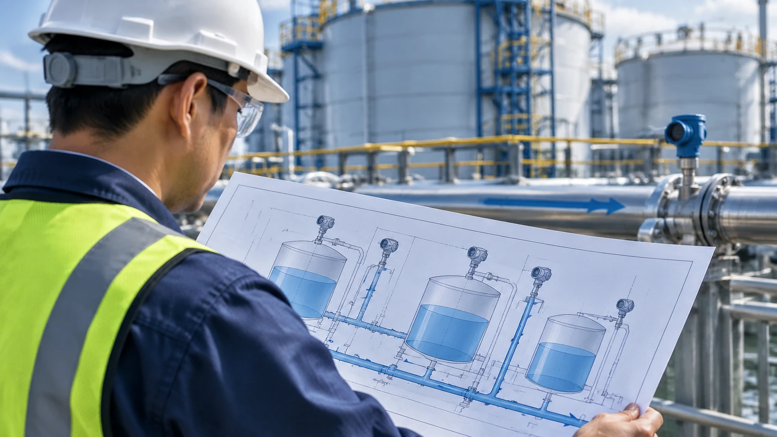
Choosing the right level meter for a vessel connected to a flow line depends on the fluid characteristics and environmental conditions. The following table provides a general selection guide:
| Application Detail | Recommended Technology | Why? |
| :— | :— | :— |
| High-Pressure Separator | Guided Wave Radar | Unaffected by gas phase changes and high pressure. |
| Corrosive Chemical Tank | Non-contact Radar | No moving parts or wetted materials to corrode. |
| Open Water Basin | Ultrasonic | Cost-effective for large, non-volatile surfaces. |
| Deep Underground Sump | Hydrostatic (Submersible) | Easy to deploy in deep, narrow spaces. |
| Foaming Liquids | Guided Wave Radar | The probe guides the signal through foam to the actual liquid surface. |
Installation Guidelines for Level Sensors Near Flow Lines
The way a flow line enters a vessel significantly impacts the accuracy of level measurement. High-velocity entry can create turbulence, foam, and surface ripples that interfere with sensor signals.
1. Avoid the Inlet Path: Never install a level sensor directly above the point where the flow line discharges into the tank. The falling liquid will cause false readings or signal scattering.
2. Use Stilling Wells: If the flow line causes significant turbulence, a stilling well (a vertical pipe inside the tank) can be used to create a calm surface for the radar or ultrasonic sensor to measure.
3. Consider Nozzle Height: For radar and ultrasonic units, ensure the mounting nozzle is short enough that it does not interfere with the sensor's "dead zone" or blocking distance.
4. Grounding: In flow lines carrying hydrocarbons, static electricity can build up. Ensure all instrumentation is properly grounded according to industrial standards (e.g., ATEX or IECEx) to prevent ignition risks.
Limitations and Operational Challenges
While modern instrumentation is highly advanced, certain conditions in flow line systems present ongoing challenges:
* Paraffin and Scale Buildup: In oil flow lines, wax or scale can accumulate on the internal walls and eventually on the level sensor probes. Regular maintenance and the use of non-contact sensors can mitigate this.
* Slug Flow: Sometimes, a flow line delivers "slugs" of liquid followed by large volumes of gas. This rapid change in volume can overwhelm a level control system if the sensor has a slow response time.
* Temperature Fluctuations: Rapid temperature changes in the fluid coming from a flow line can affect the speed of sound, requiring temperature-compensated ultrasonic sensors or the use of radar, which is immune to temperature shifts.
Frequently Asked Questions (FAQ)
Q: What is the difference between a flow line and a pipeline?
A: A flow line is typically a smaller-diameter pipe used within a production field to move raw fluids from a source to the first processing stage. A pipeline usually refers to long-distance transport of processed fluids between facilities or regions.
Q: Can I use a level switch instead of a continuous level meter for a flow line tank?
A: Level switches are excellent for high-level alarms or overfill protection. However, for process control and understanding the inflow rate from a flow line, a continuous level meter (like radar or ultrasonic) is preferred.
Q: How does foam affect level measurement in flow line systems?
A: Foam can absorb ultrasonic signals, leading to a "loss of echo." Radar is more resistant to foam, but thick, dense foam may still require guided wave radar technology to ensure the signal reaches the liquid interface.
Q: What materials are best for flow line level sensors?
A: This depends on the fluid. For acidic or corrosive fluids, PTFE or PVDF coatings are common. For high-pressure oil and gas applications, 316L stainless steel or Hastelloy is often required for wetted parts.
By understanding what is a flow line and the dynamics of the fluids it carries, engineers can better design the monitoring systems that keep industrial processes running. For detailed technical specifications on radar, ultrasonic, and hydrostatic sensors suitable for these applications, professionals should consult the Main Page of their equipment provider to ensure the selected technology meets the specific demands of their process environment.