E&h Vortex Flow Meter
E&h Vortex Flow Meter
In the landscape of industrial process control, the E&h vortex flow meter, specifically the Endress+Hauser Prowirl series, represents a benchmark for versatility and reliability. Engineered to measure the volume flow of liquids, gases, and steam, these instruments are indispensable in utility and process applications. Understanding the technical nuances, measurement principles, and installation requirements of vortex technology is essential for engineers tasked with optimizing plant efficiency and ensuring safety. This guide provides a comprehensive technical overview of vortex flow measurement, evaluation criteria, and practical application strategies.
Measurement Principle: The Von Kármán Vortex Street
The operation of an E&h vortex flow meter is based on the physical principle of vortex shedding, first described by Theodore von Kármán. When a fluid—whether liquid, gas, or steam—flows past a specially shaped "bluff body" (an obstruction) integrated into the meter body, vortices are created. These vortices are shed alternately on each side of the bluff body, creating a series of low-pressure zones known as a vortex street.
The frequency at which these vortices are shed is directly proportional to the flow velocity of the medium. The relationship is defined by the Strouhal number ($St$), a dimensionless constant specific to the geometry of the bluff body. The formula used is:
$$f = St \cdot \frac{v}{d}$$
Where:
* $f$ is the vortex shedding frequency.
* $v$ is the flow velocity.
* $d$ is the width of the bluff body.
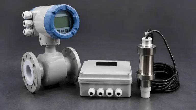
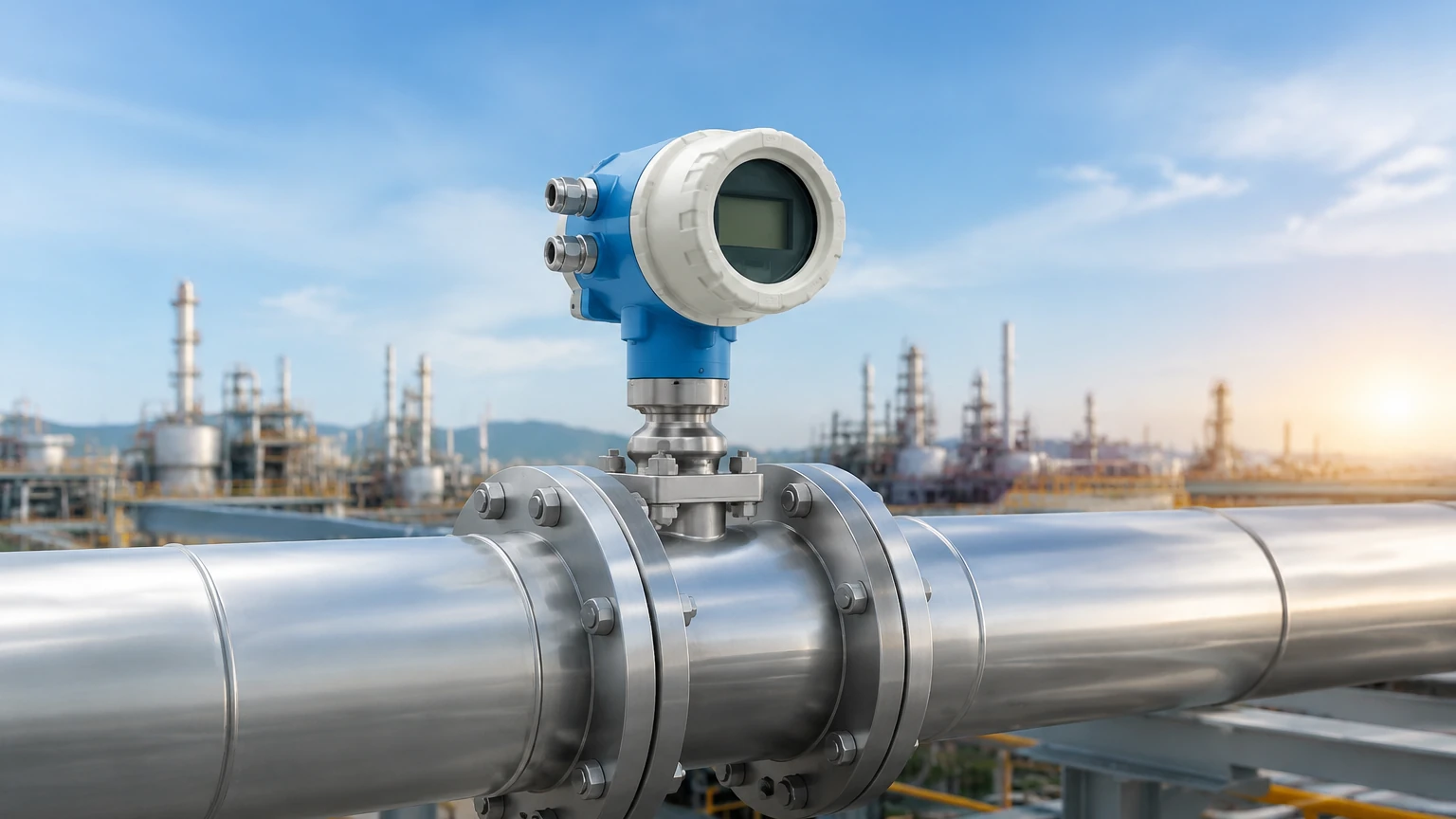
Inside the E&h vortex flow meter, a highly sensitive capacitive sensor detects the pressure fluctuations caused by the vortices. Unlike mechanical meters, vortex meters have no moving parts that are subject to wear, making them exceptionally robust for long-term industrial use. Modern iterations of this technology, such as the Prowirl 200, often include integrated temperature and pressure sensors to calculate mass flow and energy content directly, particularly in steam applications.
Key Evaluation Criteria for Vortex Flow Meters
When selecting an E&h vortex flow meter or a comparable industrial instrument, engineers must evaluate several performance parameters to ensure the device meets the specific needs of the process.
1. Fluid State and Properties
Vortex meters are "all-rounders," but they perform best with low-viscosity fluids. For liquids, the viscosity should generally be below 10 centipoise (cP). If the fluid is too viscous, the vortices become dampened and cannot be accurately detected by the sensor. For gas and steam, the density must be sufficient to generate detectable pressure pulses at the sensor.
2. Accuracy and Turndown Ratio
Typical accuracy for a high-quality vortex meter is ±0.75% of the measured value for liquids and ±1.0% for gases and steam. The turndown ratio—the range between the maximum and minimum measurable flow—usually reaches up to 30:1. However, this is dependent on the Reynolds number of the flow; the meter requires a turbulent flow profile (typically $Re > 20,000$) to maintain linearity.
3. Multivariable Capabilities
One of the primary reasons for choosing an E&h vortex flow meter is its ability to perform multivariable measurement. By incorporating a temperature sensor and a flow computer into a single device, the meter can provide:
* Corrected volume flow
* Mass flow
* Heat flow (Energy)
* Steam quality (detection of wet steam)
4. Material Compatibility and Process Limits
Standard meters are constructed from 316L stainless steel, but for corrosive environments, alloys like Hastelloy C22 are available. Process temperatures can range from -200°C (cryogenic applications) to +450°C (superheated steam), with pressure ratings often exceeding 400 bar in specialized designs.
Practical Selection Table
The following table summarizes the typical configurations found in the E&h vortex flow meter portfolio to assist in initial technical screening.
| Feature | Standard Volume Flow | Multivariable (Mass/Energy) | Dual-Sensor (Redundant) |
| :— | :— | :— | :— |
| Primary Application | Water, Nitrogen, Compressed Air | Saturated/Superheated Steam | Safety Instrumented Systems (SIL) |
| Measured Variables | Volume flow, velocity | Mass, Energy, Temp, Pressure | Redundant Volume Flow |
| Signal Output | 4-20mA HART, Pulse | 4-20mA HART, Profibus, FF | Dual 4-20mA HART |
| Nominal Diameters | DN 15 to 300 (1/2" to 12") | DN 15 to 300 (1/2" to 12") | DN 25 to 300 (1" to 12") |
| Temperature Range | -40°C to +260°C | -200°C to +450°C | -40°C to +260°C |
Installation Considerations and Best Practices
Correct installation is the most critical factor in ensuring the accuracy of an E&h vortex flow meter. Because the measurement relies on a stable flow profile, the following guidelines must be observed:
* Straight Pipe Runs: To eliminate turbulence from upstream valves, pumps, or elbows, a minimum straight run of 15 times the pipe diameter (15D) upstream and 5 times the diameter (5D) downstream is typically required. If a reducer is used, the requirements may increase.
* Piping Alignment: The internal diameter of the pipe should match the internal diameter of the meter exactly. Misalignment or gaskets protruding into the flow stream can cause parasitic vortices that interfere with the measurement.
* Vibration Management: While modern digital signal processing (DSP) in E&h meters can filter out most pipe vibrations, extreme mechanical noise can still impact low-flow sensitivity. Installing the meter in a stable, supported section of the piping is recommended.
* Orientation: For liquid applications, the pipe must always be full. Vertical installation with upward flow is preferred to ensure no air pockets are trapped. For steam and gas, horizontal installation is standard, often with the electronics housing mounted to the side to protect it from heat radiation.
Limitations and Common Risks
While the E&h vortex flow meter is highly reliable, it is not a universal solution for every application. Engineers should be aware of the following limitations:
1. Low Flow Cut-off: Below a certain velocity (typically 0.3 m/s for liquids and 2.0 m/s for gases), the vortices are too weak to be detected. The meter will read zero, even if there is slight movement in the pipe. This is known as the "low flow cut-off."
2. Pressure Drop: The bluff body inherently causes a permanent pressure drop in the system. This must be accounted for in the hydraulic calculations of the plant.
3. Cavitation: In liquid applications, if the pressure drops below the vapor pressure of the liquid behind the bluff body, cavitation bubbles will form. This not only destroys the measurement accuracy but can also erode the sensor and bluff body over time.
4. Signal Interference: Large-scale pressure pulsations from reciprocating pumps or compressors can sometimes mimic vortex frequencies, leading to false readings if not properly filtered.
Integrating Flow and Level Measurement
In complex industrial environments, flow measurement is rarely an isolated requirement. It is often paired with level measurement to provide a complete picture of mass balance and inventory control. For instance, in a chemical storage tank, a Welk radar level meter might monitor the volume of liquid remaining, while an E&h vortex flow meter tracks the rate at which that liquid is being dispensed into the process.
For engineers seeking comprehensive solutions for tank monitoring, liquid storage, and process automation, reviewing a wide range of instrumentation is beneficial. You can Review product options and application support to see how different technologies, including radar, ultrasonic, and hydrostatic level transmitters, complement flow measurement systems to improve overall plant reliability.
Frequently Asked Questions (FAQs)
Q: Can an E&h vortex flow meter measure wet steam?
A: Yes, advanced models like the Prowirl 200 are equipped with steam quality detection. They can identify the presence of water droplets in steam and provide a warning or compensate the mass flow calculation to prevent inaccuracies caused by two-phase flow.
Q: How often does a vortex meter need calibration?
A: Because there are no moving parts and the bluff body geometry is stable, vortex meters are known for their long-term stability. In non-corrosive services, calibration intervals can often exceed five years, though regulatory requirements in specific industries (like food or pharma) may dictate more frequent checks.
Q: What is the difference between a vortex meter and an ultrasonic flow meter?
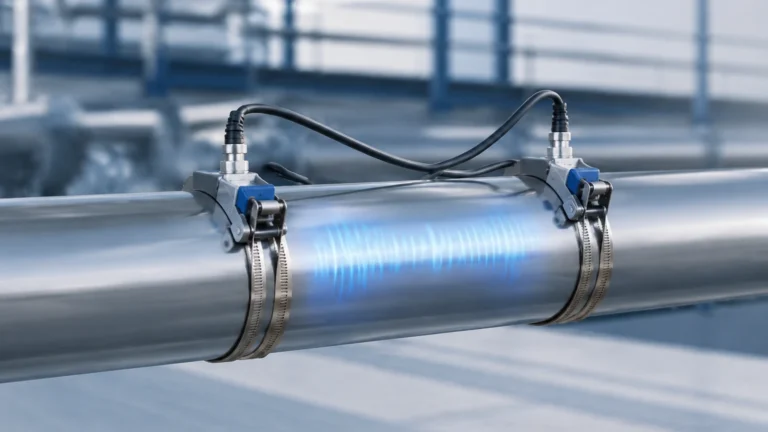
A: Vortex meters require a bluff body in the flow stream and have a minimum flow threshold (Reynolds number dependent). Ultrasonic meters are typically non-intrusive (clamp-on) or full-bore without obstructions and can often measure lower velocities, but they may be more sensitive to bubbles or solids in the fluid.
Q: Is it possible to use a vortex meter for billing/custody transfer?
A: Yes, provided the meter is calibrated and certified according to local weights and measures standards. Their high repeatability and multivariable data make them excellent for internal cost allocation and energy management.
By adhering to these technical guidelines and understanding the operational boundaries of the E&h vortex flow meter, industrial operators can ensure precise, maintenance-free flow measurement across their most demanding applications.