Electrical Conductivity Sensor
Electrical Conductivity Sensor
In the landscape of industrial process control, the ability to monitor liquid composition in real-time is as critical as measuring volume or pressure. An electrical conductivity sensor serves as a fundamental analytical tool, providing immediate insight into the ionic concentration of a solution. Whether used for ensuring the purity of boiler feed water or monitoring the concentration of caustic cleaning agents in a Food and Beverage Clean-in-Place (CIP) system, understanding the principles, selection criteria, and installation nuances of these sensors is essential for plant engineers and system integrators.
While level measurement instruments—such as those found on our Main Page—quantify the amount of substance present, conductivity sensors qualify what that substance is and how it is changing chemically. This guide provides a comprehensive technical overview of conductivity measurement technology for industrial applications.
Measurement Principles of Electrical Conductivity
Electrical conductivity is the measure of a solution's ability to conduct an electrical current. In aqueous solutions, this current is carried by dissolved ions (such as salts, acids, or bases). The more ions present, the higher the conductivity. The standard unit of measurement is Siemens per meter (S/m), though in industrial practice, microsiemens per centimeter (µS/cm) or millisiemens per centimeter (mS/cm) are more common.
There are two primary methods used by an electrical conductivity sensor to determine this value: contacting and inductive (toroidal).
1. Contacting Conductivity Measurement
In a contacting sensor, two or more electrodes are placed in direct contact with the process liquid. An alternating voltage is applied to the electrodes, and the resulting current is measured. According to Ohm’s Law, the resistance of the solution can be calculated, and its reciprocal is the conductance.
To standardize the measurement regardless of the sensor's physical size, a "Cell Constant" (K) is used. The cell constant is the ratio of the distance between the electrodes (L) to the cross-sectional area of the electrodes (A).
* Two-Electrode Sensors: Best suited for low-conductivity applications like pure and ultrapure water. However, they are susceptible to "polarization errors" and fouling, where a buildup on the electrode surface adds artificial resistance to the circuit.
* Four-Electrode Sensors: These use two electrodes to drive the current and two separate electrodes to measure the voltage drop. This design minimizes the impact of electrode fouling and cable resistance, making them suitable for a wider range of medium-to-high conductivity applications.
2. Inductive (Toroidal) Conductivity Measurement
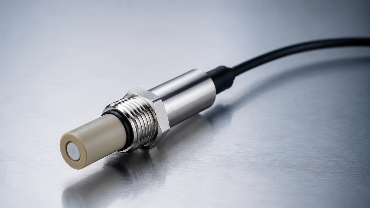
Inductive sensors do not use electrodes in contact with the liquid. Instead, they consist of two wire-wound metal toroids (coils) encapsulated in a chemically resistant plastic (such as PEEK or PFA). One coil acts as a transmitter, creating an alternating magnetic field that induces an ionic current in the surrounding liquid. This liquid current, in turn, induces a signal in the second "receiver" coil.
Because there are no electrodes to foul or corrode, the inductive electrical conductivity sensor is the preferred choice for aggressive chemicals, high-salinity brines, and heavy industrial wastewater.
Practical Selection Criteria
Choosing the right sensor requires an analysis of the chemical environment, the expected conductivity range, and the physical constraints of the installation. The following table provides a comparison to assist in the selection process.
Selection Table: Sensor Type Comparison
| Feature | Contacting (2-Electrode) | Contacting (4-Electrode) | Inductive (Toroidal) |
| :— | :— | :— | :— |
| Measurement Range | 0.01 µS/cm to 1,000 µS/cm | 10 µS/cm to 500 mS/cm | 100 µS/cm to 2,000 mS/cm |
| Best Application | Ultrapure water, condensate | General process water | Acids, bases, slurries, brine |
| Fouling Sensitivity | High | Moderate | Very Low |
| Chemical Resistance | Limited by electrode metal | Moderate | High (Plastic encapsulated) |
| Maintenance Needs | High (Frequent cleaning) | Moderate | Low |
| Pipe Size Requirement | Small (can fit in 1/2" NPT) | Moderate | Large (requires 2" or larger) |
Installation Considerations
To ensure an electrical conductivity sensor provides accurate and repeatable data, the physical installation must account for fluid dynamics and electrical interference.
1. Avoidance of Air Pockets and Bubbles
Conductivity measurement requires a continuous liquid path between electrodes or through the center of a toroidal sensor. Air is an insulator; if bubbles accumulate on the electrode surface or air pockets form in the sensor chamber, the reading will drop significantly, regardless of the actual liquid concentration. Sensors should be installed in upward-flowing vertical pipes or on the side of horizontal pipes—never at the top where air collects.
2. The "Wall Effect" in Inductive Sensors
Inductive (toroidal) sensors generate a magnetic field that extends beyond the physical body of the sensor. If the sensor is placed too close to a metallic pipe wall, the field will interact with the metal, causing measurement errors. Manufacturers specify a minimum clearance (usually 20mm to 50mm) from pipe walls. If space is tight, plastic pipe inserts or specialized calibration factors must be used.
3. Temperature Compensation
Conductivity is highly temperature-dependent. As temperature increases, the mobility of ions increases, typically raising conductivity by approximately 2% per degree Celsius. Most industrial electrical conductivity sensors include an integrated temperature element (like a Pt100 or Pt1000). The transmitter then applies a compensation algorithm to report the conductivity at a reference temperature, usually 25°C.
4. Grounding and Interference
In large industrial tanks or piping systems, stray electrical currents (ground loops) can interfere with the sensitive millivolt signals of a conductivity sensor. Proper grounding of the sensor housing and the use of shielded cabling are mandatory to prevent signal noise.
Limitations and Common Risks
While robust, conductivity sensors are not "set and forget" devices. Users should be aware of the following risks:
* Polarization: In contacting sensors, if the frequency of the alternating current is too low or the conductivity is too high, ions can build up near the electrodes, creating a "capacitance" effect that skews the reading. High-quality transmitters automatically adjust the frequency to mitigate this.
* Coating and Scaling: In applications like hard water treatment or wastewater, calcium carbonate or oils can coat the electrodes. This increases the measured resistance, leading to an artificially low conductivity reading. Inductive sensors are largely immune to this, but even they can fail if the "hole" in the toroid becomes completely plugged with solids.
* Non-Specific Measurement: Conductivity is a "bulk" measurement. It tells you the total ionic content but cannot distinguish between different types of ions. For example, a sensor cannot tell the difference between a 5% Sodium Chloride solution and a 5% Potassium Chloride solution if they produce the same conductivity value.
Frequently Asked Questions (FAQ)
Q: How often should an electrical conductivity sensor be calibrated?
A: This depends on the application. In ultrapure water, sensors may remain stable for months. In harsh chemical processes, monthly or even weekly verification against a standard solution is recommended. Always perform a two-point calibration (Zero and Slope) for the best accuracy.
Q: Can I use a contacting sensor for concentrated sulfuric acid?
A: It is not recommended. Concentrated acids are highly corrosive to most electrode metals and have high conductivity levels that would quickly polarize a standard contacting sensor. An inductive (toroidal) sensor made of PFA or PEEK is the standard choice for such applications.
Q: What is the difference between Conductivity and TDS?
A: Total Dissolved Solids (TDS) is a measure of the mass of dissolved material. Transmitters often calculate TDS by multiplying the conductivity value by a conversion factor (typically between 0.5 and 0.9). This is an estimate, as the actual factor varies based on the specific salts present in the water.
Q: How do I clean a fouled electrode?
A: For mineral scale, a 5% hydrochloric acid soak is usually effective. For organic oils or greases, a mild detergent or isopropyl alcohol can be used. Never use abrasive materials (like sandpaper) on electrodes, as this changes the cell constant by altering the surface area.
Integration with Level Measurement Systems
In many industrial setups, conductivity sensors work in tandem with level meters. For instance, in an interface detection application, a radar or ultrasonic level meter tracks the total volume in a tank, while an electrical conductivity sensor detects the transition point between an aqueous layer and an organic solvent layer.
By integrating these two data points, operators gain a complete picture of both the quantity and the quality of their process fluids. For more information on selecting the appropriate hardware for your specific tank or pipe configuration, you can review product options and application support on our Main Page.
Conclusion
The electrical conductivity sensor is an indispensable component of modern process automation. By understanding the fundamental differences between contacting and inductive technologies, engineers can select a solution that balances accuracy with maintenance requirements. Proper installation—focused on avoiding air entrapment and ensuring correct temperature compensation—remains the most critical factor in achieving long-term reliability in the field.