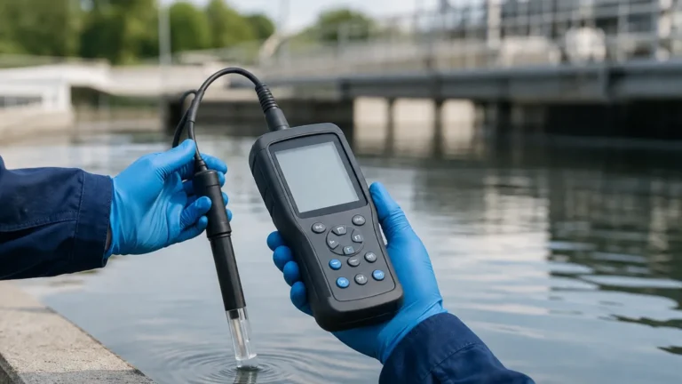
Electrical Pressure Unit
Electrical Pressure Unit
In the context of industrial automation and process control, the term "electrical pressure unit" often serves a dual purpose. Historically and fundamentally in physics, it refers to voltage—the force that drives electrical current through a circuit. However, for engineers and technicians working with instrumentation, it more frequently refers to the electrical output signals used by pressure and level transmitters to represent physical pressure measurements. Understanding how these electrical units correlate with physical pressure is essential for accurate data acquisition and system integration.
At Welk, we specialize in the manufacturing of advanced level measurement instruments, including hydrostatic level transmitters that rely heavily on the precise conversion of physical pressure into standardized electrical units. This guide provides a technical overview of these units, their measurement principles, and how to select the appropriate electrical interface for industrial applications.
Understanding the Relationship Between Electrical and Physical Pressure
To effectively use a pressure or level sensor, one must understand the transduction process. A pressure sensor (or transmitter) contains a sensing element—often a piezoresistive silicon chip or a ceramic diaphragm—that deforms under physical pressure. This mechanical deformation is converted into a change in electrical resistance or capacitance, which the internal electronics then process into a standardized electrical signal.
The Physics of Electrical Pressure (Voltage)
In basic electrical theory, voltage is the electrical pressure unit. Measured in Volts (V), it represents the potential difference between two points. Just as water pressure pushes liquid through a pipe, voltage pushes electrons through a conductor. In industrial sensing, this "electrical pressure" is modulated to provide a readable value for a Programmable Logic Controller (PLC) or a Distributed Control System (DCS).
Physical Pressure Units
Before converting to an electrical signal, the instrument must measure physical pressure. Common units include:
- Pascal (Pa) / Kilopascal (kPa) / Megapascal (MPa): The SI unit of pressure.
- Bar: A metric unit widely used in industrial hydraulics and pneumatics (1 bar = 100,000 Pa).
- PSI (Pounds per Square Inch): The primary imperial unit for pressure.
- mH2O (Meters of Water Column): Often used in hydrostatic level measurement to represent the pressure exerted by a specific depth of water.
Common Electrical Output Units in Industrial Sensing
When selecting a transmitter from the Main Page of an instrumentation catalog, the choice of electrical output is as critical as the pressure range itself. There are three primary categories of electrical units used to transmit pressure data.
1. Current Loop (4-20mA)
The 4-20mA current loop is the global standard for industrial process control. In this configuration, 4mA represents the zero-scale pressure (e.g., 0 bar), and 20mA represents the full-scale pressure (e.g., 10 bar).
Advantages:
- Immunity to Noise: Because the signal is current-based, it is highly resistant to electromagnetic interference (EMI).
- Long Distance: Current signals do not suffer from voltage drops over long cable runs, making them ideal for remote tank farms.
- Fault Detection: If the wire breaks, the current drops to 0mA, which the controller recognizes as a fault (since the minimum valid signal is 4mA).
2. Voltage Signals (0-5V, 0-10V, 1-5V)
Voltage-based electrical pressure units are common in laboratory settings and localized industrial equipment where cable runs are short.
Advantages:
- Low Power Consumption: Voltage signals generally require less power than current loops.
- Simplicity: Many microcontrollers and simple data loggers can read voltage directly without a shunt resistor.
Limitations:
- Voltage Drop: Over long distances, the resistance of the wire causes the voltage to drop, leading to measurement errors.
- Sensitivity to Noise: Voltage signals are more susceptible to interference from nearby motors and power lines.
3. Digital and Bus Protocols (RS485/Modbus, HART)
Modern "smart" transmitters use digital units. While the physical layer might still use voltage or current, the data is transmitted as binary code.
- HART: Superimposes a digital signal on a 4-20mA loop.
- RS485/Modbus: Uses differential voltage to transmit data packets, allowing for multiple sensors on a single pair of wires.
Measurement Principles: From Physical to Electrical
To ensure accuracy, the conversion from a physical pressure unit to an electrical pressure unit must be linear. For a hydrostatic level transmitter, the relationship is governed by the formula:
P = ρ × g × h
Where:
- P is the hydrostatic pressure (Pa).
- ρ (rho) is the density of the liquid (kg/m³).
- g is the gravitational acceleration (approximately 9.81 m/s²).
- h is the height of the liquid (m).
The transmitter measures P and outputs a proportional electrical signal. For example, if a 10-meter deep water tank is measured by a 4-20mA sensor calibrated for 0-10m:
- At 0 meters (0 kPa), the output is 4mA.
- At 5 meters (~49 kPa), the output is 12mA.
- At 10 meters (~98 kPa), the output is 20mA.
Practical Selection Table for Pressure and Level Transmitters
When choosing an instrument, engineers must match the electrical output to the environment and the control system requirements.
| Electrical Output | Ideal Application | Maximum Distance | Noise Resistance | Power Requirement |
| :— | :— | :— | :— | :— |
| 4-20mA | General Industrial, Outdoor Tanks | Up to 1,000m+ | High | Moderate (Loop Powered) |
| 0-10V | HVAC, Indoor Machinery | < 15m | Low | Low |
| 0-5V | Battery-powered IoT Devices | < 10m | Low | Very Low |
| RS485/Modbus | Multi-sensor Networks | Up to 1,200m | Very High | Moderate |
| HART | Asset Management/Diagnostics | Up to 1,000m | High | Moderate |
Installation Considerations for Electrical Pressure Sensors
Proper installation ensures that the electrical pressure unit accurately reflects the physical state of the process. Below are key engineering considerations:
1. Wiring and Shielding
To prevent electrical noise from distorting the signal, shielded twisted-pair cables should be used. The shield should be grounded at only one end (usually the controller end) to prevent ground loops, which can introduce significant errors in voltage-based signals.
2. Loop Resistance
For 4-20mA systems, the power supply must be sufficient to overcome the total loop resistance, which includes the wire resistance and the input impedance of the controller. If the resistance is too high, the transmitter will not be able to reach the 20mA full-scale output.
3. Environmental Protection
Electrical connections must be protected from moisture and corrosive atmospheres. For submersible hydrostatic sensors, the cable often includes a vent tube to compensate for atmospheric pressure changes. Ensuring this tube remains unobstructed is vital for accurate "gauge pressure" readings.
Limitations and Troubleshooting
Despite the reliability of modern electronics, several factors can affect the accuracy of electrical pressure units:
- Temperature Drift: Electronics are sensitive to temperature. High-quality transmitters include internal temperature compensation to ensure the mA or V output remains stable across a wide operating range (typically -20°C to +80°C).
- Signal Clipping: If the physical pressure exceeds the sensor's rated range, the electrical signal will "clip" at its maximum (e.g., 20.5mA or 10.5V), indicating an over-range condition.
- Electromagnetic Interference (EMI): Large motors or VFDs (Variable Frequency Drives) can induce voltages in sensor cables. Using 4-20mA signals and proper conduit significantly mitigates this risk.
Frequently Asked Questions (FAQ)
Q: Can I convert a voltage output sensor to a current output?
A: Yes, using a signal conditioner or transmitter module, a 0-10V signal can be converted to 4-20mA. However, it is generally more cost-effective and reliable to purchase a sensor with the native output required for your system.
Q: Why is 4mA used as the starting point instead of 0mA?
A: This is known as a "live zero." It allows the system to distinguish between a zero-pressure reading (4mA) and a broken wire or power failure (0mA).
Q: How does liquid density affect the electrical output of a level transmitter?
A: Hydrostatic transmitters measure pressure, not height directly. If the liquid density changes (e.g., switching from water to oil), the pressure exerted at the same height will change, requiring a recalibration of the electrical output scale.
Q: Is RS485 better than 4-20mA?
A: It depends on the application. RS485 allows for digital diagnostics and multiple sensors on one cable, but 4-20mA is simpler to troubleshoot with a basic multimeter and is a more universal standard across older and newer systems.
For technical specifications on specific measurement ranges and output configurations, users should consult the Main Page to review product options and application support. Selecting the right combination of physical pressure range and electrical pressure unit is the foundation of a reliable process control architecture.