Electrical Water Level Sensor
Electrical Water Level Sensor
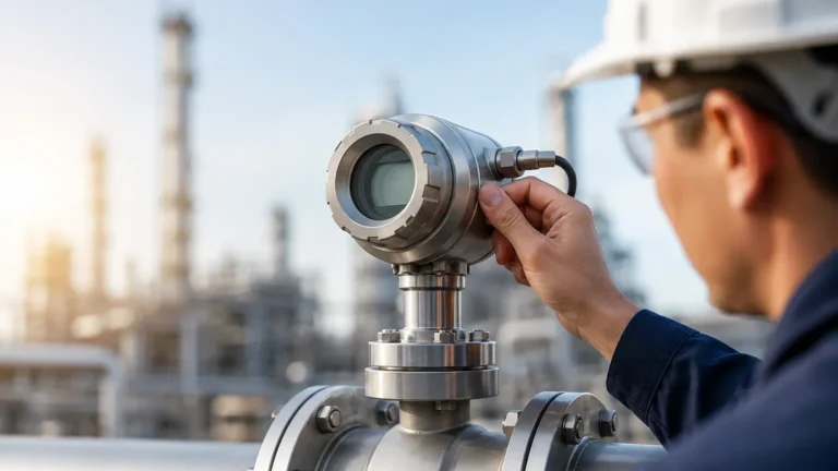
In modern industrial automation, the term "electrical water level sensor" encompasses a broad category of devices designed to convert the physical presence or height of water into a standardized electrical signal. These sensors are fundamental to process control in water treatment, chemical processing, and power generation. Unlike simple mechanical floats, electrical sensors provide the high-precision data required for PLC (Programmable Logic Controller) integration and remote monitoring systems.
Selecting the appropriate electrical water level sensor requires an understanding of the underlying measurement physics, the chemical properties of the water being measured, and the physical constraints of the installation environment. This guide examines the primary measurement principles and provides a framework for engineering selection.
Measurement Principles of Electrical Water Level Sensors
Electrical level measurement is generally divided into point-level detection (on/off) and continuous level measurement. The following technologies represent the most common methods used in industrial applications.
1. Hydrostatic Pressure Measurement
Hydrostatic sensors operate on the principle that the pressure at the bottom of a liquid column is directly proportional to the height of that liquid. The relationship is defined by the formula: $P = \rho \cdot g \cdot h$, where $P$ is pressure, $\rho$ is the density of the liquid, $g$ is gravity, and $h$ is the height of the liquid.
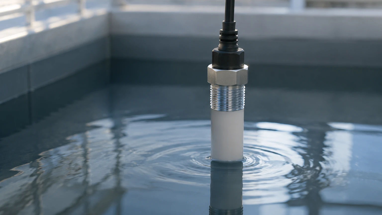
In an electrical water level sensor of this type, a sensing diaphragm (often made of stainless steel or ceramic) deforms under the weight of the water. This deformation is measured by a strain gauge or capacitive element, which converts the mechanical stress into an electrical signal, typically 4-20mA or RS485 Modbus. For vented tanks, a capillary tube within the sensor cable allows the sensor to compensate for changes in atmospheric pressure.
2. Ultrasonic (Time-of-Flight)
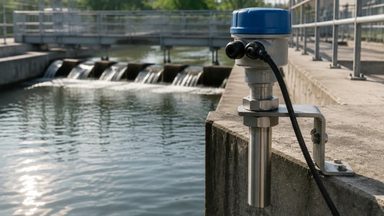
Ultrasonic sensors are non-contact electrical devices. They emit high-frequency sound pulses (typically 40 kHz to 200 kHz) from a transducer located at the top of the vessel. The pulses reflect off the water surface and return to the sensor. By measuring the time interval between transmission and reception, the sensor calculates the distance to the water surface.
Because sound speed is affected by air temperature, these sensors usually include an integrated temperature probe to perform real-time compensation. This technology is ideal for corrosive liquids where contact-based sensors might degrade.
3. Radar (Microwave)
Similar to ultrasonic sensors, radar level meters use time-of-flight but employ electromagnetic waves (microwaves) rather than sound. Radar waves travel at the speed of light and are largely unaffected by air temperature, pressure, or the presence of vapors and dust. Guided wave radar (GWR) uses a probe to direct the signal, while non-contact radar transmits signals through the air. These are considered the gold standard for high-accuracy industrial applications.
4. Capacitance
Capacitive sensors treat the water and the tank (or a second probe) as two plates of a capacitor. As the water level rises, it displaces air. Since water has a much higher dielectric constant ($ε ≈ 80$) than air ($ε ≈ 1$), the total capacitance of the system changes linearly with the level. An integrated circuit converts this change in capacitance into a standard electrical output.
5. Conductivity
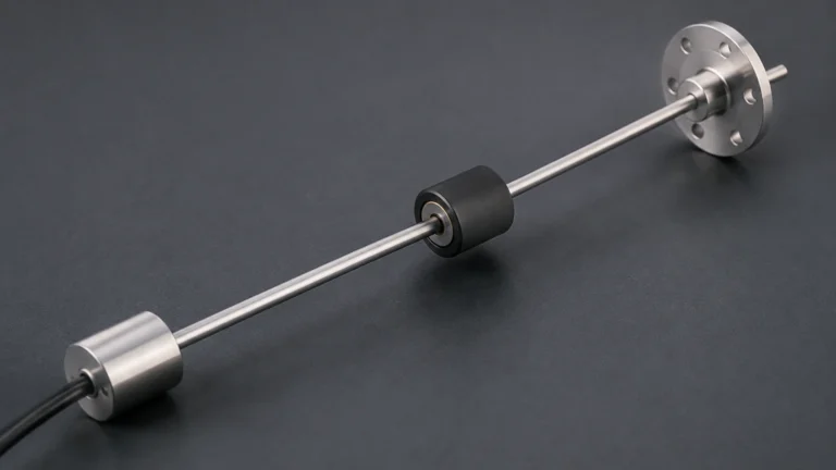
Conductive sensors are primarily used for point-level detection. They utilize the electrical conductivity of water to complete a circuit. When the water reaches a specific electrode, a small current flows between the electrode and the reference (often the tank wall), triggering a relay or a digital signal. These are common in boiler water control and sump pump management.
Technical Selection Criteria
Choosing the right electrical water level sensor involves balancing accuracy requirements against environmental challenges. For a comprehensive overview of available technologies and specific model specifications, engineers should consult the Main Page of professional instrumentation providers.
| Technology | Typical Accuracy | Measurement Range | Key Advantage | Primary Limitation |
| :— | :— | :— | :— | :— |
| Hydrostatic | ±0.1% to ±0.5% | Up to 200m | Simple installation, low cost | Sensitive to density changes |
| Ultrasonic | ±0.25% | 0.2m to 20m | Non-contact, low maintenance | Affected by foam and heavy vapor |
| Radar | ±1mm to ±3mm | Up to 70m+ | Highest precision, immune to vapor | Higher initial investment |
| Capacitance | ±0.5% to ±1% | Up to 5m | No moving parts, high temp/pressure | Requires constant dielectric |
| Conductivity | N/A (Point) | Fixed points | Extremely robust and cheap | Only for conductive liquids |
Installation and Engineering Considerations
Proper installation is as critical as sensor selection. Even the most accurate electrical water level sensor will provide erroneous data if installed incorrectly.
Mounting and Positioning
* Dead Zones (Blocking Distance): For ultrasonic and radar sensors, there is a minimum distance near the transducer face where measurements cannot be taken. Ensure the sensor is mounted high enough that the water level never enters this zone.
* Stilling Wells: In tanks with high turbulence or surface agitation (e.g., near an inlet pipe), a stilling well—a vertical pipe that dampens waves—can provide a stable surface for measurement.
* Submersible Placement: For hydrostatic sensors used in deep wells or reservoirs, the sensor should be placed at least 0.5 meters above the bottom to avoid silt and sediment accumulation, which can clog the sensing diaphragm.
Electrical Integration
Most industrial sensors output a 4-20mA current loop. This is preferred over voltage signals (like 0-10V) because current loops are immune to electrical noise over long cable runs and can detect a broken wire (indicated by a 0mA reading). Digital protocols like RS485 Modbus or HART are increasingly common, allowing for the transmission of secondary data such as internal sensor temperature and diagnostic alerts.
Cable Management
For submersible sensors, the cable often contains a vent tube. It is vital that this tube is not kinked or blocked. Termination boxes should include a desiccant or a breathable membrane to prevent moisture from entering the vent tube and causing internal condensation, which can lead to sensor drift or failure.
Limitations and Common Risks
While electrical water level sensors are highly reliable, certain conditions can compromise their performance:
1. Media Buildup: In wastewater applications, fats, oils, and grease (FOG) can coat the sensing elements of hydrostatic or capacitive probes. This buildup adds weight or changes the dielectric properties, leading to inaccurate readings. Non-contact sensors are usually preferred in these scenarios.
2. Vapor and Foam: Ultrasonic pulses can be absorbed by thick foam or refracted by heavy steam/vapor layers. In such environments, radar or hydrostatic sensors are more effective.
3. Electromagnetic Interference (EMI): In facilities with large motors or variable frequency drives (VFDs), electrical noise can interfere with low-voltage sensor signals. Using shielded cables and ensuring proper grounding is mandatory.
4. Temperature Extremes: Rapid temperature changes can cause thermal expansion in sensor components. While most high-end sensors include temperature compensation, extreme heat (above 80°C) may require specialized cooling fins or remote electronics.
Frequently Asked Questions (FAQ)
Q: Can an electrical water level sensor be used for liquids other than water?
A: Yes, but with caveats. Hydrostatic sensors must be recalibrated for the specific gravity of the liquid. Capacitive sensors require a consistent dielectric constant. Non-contact radar is generally the most versatile for different liquid types.
Q: What is the difference between a level transmitter and a level switch?
A: A level switch (like a conductivity probe) provides a discrete signal (on/off) at a specific point. A level transmitter provides a continuous electrical signal (e.g., 4-20mA) representing the exact level across a range.
Q: How often should these sensors be calibrated?
A: In critical industrial processes, annual calibration is standard. However, in stable water treatment applications, hydrostatic and radar sensors may maintain accuracy for several years without adjustment. Sensors in fouling environments may require monthly cleaning and verification.
Q: Is a vented cable always necessary for submersible sensors?
A: For gauge pressure measurements (where you want to ignore atmospheric pressure changes), a vented cable is necessary. If the sensor is absolute (sealed), it will measure the water pressure plus the atmospheric pressure, which requires a second barometric sensor at the surface to calculate the true level.
Conclusion
The implementation of an electrical water level sensor is a foundational step in optimizing industrial water management. By understanding the trade-offs between contact and non-contact technologies, and by adhering to rigorous installation standards, engineers can ensure long-term data reliability and process safety. For specific application support and to review detailed product options, visiting the Main Page of a dedicated manufacturer is recommended to match the technology to the specific rigors of the operating environment.