Echo Touch
Echo Touch
In the field of industrial automation and process control, the term "echo touch" represents the intersection of sophisticated signal processing and user-centric configuration. Modern level measurement instruments, particularly those utilizing ultrasonic and radar technologies, rely on the transmission and reception of pulses—the "echo"—to determine the distance to a material surface. The "touch" aspect refers to the evolution of local user interfaces, allowing engineers and technicians to calibrate, troubleshoot, and monitor these complex systems directly at the point of measurement.
For professionals managing water treatment facilities, chemical processing plants, or oil and gas storage, understanding how these devices interpret signals is critical for ensuring operational safety and efficiency. This guide explores the principles of echo-based measurement, the nuances of signal processing, and the practical considerations for selecting and installing these instruments.
Measurement Principles: Ultrasonic vs. Radar
Before selecting a device with an echo touch interface, it is essential to understand the underlying physics of the measurement. Most non-contact level transmitters operate on the Time-of-Flight (ToF) principle.
Ultrasonic Level Measurement
Ultrasonic sensors emit high-frequency sound pulses (typically between 20 kHz and 200 kHz). These sound waves travel through the air, reflect off the surface of the liquid or solid, and return to the transducer. The device calculates the distance based on the time elapsed and the speed of sound in the medium.
* Medium: Requires a gas (usually air) to propagate.
* Speed: Approximately 343 m/s (1,125 ft/s) at 20°C.
* Sensitivity: Highly dependent on air temperature, humidity, and pressure, as these factors change the speed of sound.
Radar Level Measurement
Radar transmitters emit electromagnetic pulses, typically in the microwave frequency range (e.g., 6 GHz, 26 GHz, or 80 GHz). These pulses travel at the speed of light and reflect off the material surface based on the change in dielectric constant (εr).
* Medium: Can travel through a vacuum and is largely unaffected by gas composition.
* Speed: Approximately 300,000 km/s (186,000 miles/s).
* Sensitivity: Primarily affected by the dielectric constant of the target material; materials with higher dielectric constants provide stronger reflections.
The "Echo" in Level Measurement: Signal Processing
The core challenge in non-contact level measurement is not just receiving a signal, but identifying the *correct* signal. In a typical industrial tank, there are numerous obstructions—ladders, agitators, heating coils, and inlet pipes—that can create "false echoes."
Echo Mapping and Filtering
Modern instruments use advanced algorithms to create an echo curve or "map." This is a graphical representation of all reflections received by the sensor. The device must distinguish between the "true echo" (the liquid surface) and "noise" or "false echoes" (internal tank structures).
1. False Echo Suppression: This feature allows the user to "teach" the device which echoes are static obstructions. Once mapped, the software ignores these reflections, focusing only on the moving echo of the product level.
2. Signal-to-Noise Ratio (SNR): A higher SNR indicates a clearer distinction between the target surface and background interference. This is particularly important in applications involving foam or turbulent surfaces.
3. Echo Tracking: The software tracks the peak of the reflection as it moves up and down, ensuring that the device does not "lock onto" a fixed obstruction if the signal is momentarily lost.
The "Touch" Interface: Local Configuration
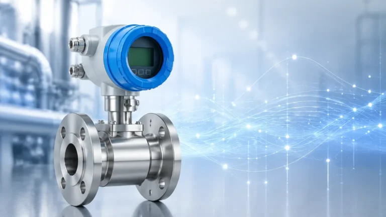
The "touch" component of modern transmitters refers to the Human-Machine Interface (HMI). Historically, level sensors were configured via complex DIP switches or required a separate handheld communicator. Today, many high-performance units feature integrated displays with touch-sensitive buttons or simplified push-button menus.
Key Benefits of Local Interfaces
* Real-time Diagnostics: Operators can view the echo curve directly on the device display to verify if the sensor is correctly identifying the liquid level.
* Simplified Calibration: Setting the "Empty" and "Full" points (4mA and 20mA positions) can be done in minutes without specialized software.
* Environmental Protection: Touch-sensitive buttons often work through a glass or plastic cover, maintaining the integrity of the NEMA 4X or IP67/68 housing in harsh environments.
For those seeking a variety of sensor types and configuration options, it is helpful to Review product options and application support on the Welk main page to understand which interface best suits specific hazardous or industrial locations.
Selection Criteria for Level Transmitters
Choosing between an ultrasonic or radar device with an echo-based interface depends on the specific requirements of the application. The following table provides a comparison for common process conditions.
| Feature | Ultrasonic Transmitters | Radar Transmitters (Non-Contact) |
| :— | :— | :— |
| Primary Application | Water, wastewater, open channels | Chemicals, oil, high-temp liquids |
| Max Range | Up to 15m (50 ft) | Up to 70m+ (230 ft+) |
| Accuracy | ±0.25% of range | ±2mm to ±5mm |
| Pressure Limit | Typically < 3 bar (43 psi) | High pressure (up to 40+ bar) |
| Temperature Limit | Typically < 80°C (176°F) | Up to 250°C+ (482°F+) |
| Effect of Foam | Significant signal dampening | Varies; high-frequency radar handles light foam better |
| Cost | Generally lower | Generally higher |

Installation Considerations and Best Practices
Even the most advanced echo touch device will fail if installed incorrectly. Proper mechanical mounting is the foundation of accurate signal processing.
1. The Dead Zone (Blocking Distance)
Every echo-based sensor has a "dead zone" directly beneath the transducer where measurements cannot be taken. This is the time required for the transducer to stop vibrating (ultrasonic) or for the electronics to switch from transmit to receive mode (radar). Ensure the maximum liquid level never enters this zone.
2. Beam Angle and Obstructions
The signal is emitted in a cone shape. The "beam angle" determines the diameter of this cone at a given distance. The installation point must be chosen so that the beam does not intercept the tank wall or internal structures before reaching the liquid.
* Calculation: If a sensor has a 10° beam angle and is 5m (16.4 ft) from the surface, the beam diameter will be approximately 0.87m (2.8 ft).
3. Nozzle Geometry
If the sensor is mounted on a nozzle, the nozzle height and diameter must be considered. A nozzle that is too narrow or too long can create internal reflections that interfere with the near-range measurement.
4. Surface Conditions
* Turbulence: If the surface is highly turbulent, the echo may be scattered. Using a stilling well or a device with faster signal processing can mitigate this.
* Vapor and Condensation: In ultrasonic applications, heavy vapor can change the speed of sound. In radar applications, heavy condensation on the sensor face can attenuate the signal.
Limitations and Common Challenges
While echo touch technology is robust, it is not a universal solution. Engineers should be aware of the following limitations:
* Vacuum Conditions: Ultrasonic sensors cannot function in a vacuum because there is no medium to carry the sound waves. Radar is the preferred choice here.
* Extremely Low Dielectric Materials: Some non-aqueous liquids (like liquid nitrogen or certain oils) have very low dielectric constants, making them difficult for radar to detect without specialized high-sensitivity electronics or guided wave radar (GWR).
* Heavy Dust or Steam: In solid level measurement, heavy dust can absorb ultrasonic pulses. High-frequency radar (80 GHz) is typically more effective at penetrating dust.
Frequently Asked Questions (FAQ)
Q: Can I use an echo-based sensor in a tank with an agitator?
A: Yes, but it requires careful selection. You must use the "False Echo Suppression" or "Background Mapping" feature to tell the device to ignore the agitator blades as they pass through the beam.
Q: How does temperature affect the "echo"?
A: For ultrasonic sensors, temperature significantly changes the speed of sound. Most sensors include an internal temperature probe to compensate for this, but for high accuracy, an external temperature sensor is often recommended. Radar is largely unaffected by temperature changes in the gas space.
Q: What is the difference between "Echo Touch" and "Guided Wave Radar"?
A: Echo touch usually refers to non-contact sensors (air-borne pulses). Guided Wave Radar (GWR) uses a physical probe (rod or cable) to guide the pulse to the surface. GWR is often more reliable in applications with heavy foam or low dielectric constants.
Q: Does the color of the liquid affect the measurement?
A: No. Unlike optical or laser sensors, ultrasonic and radar signals are not affected by the color or transparency of the material.
By understanding the relationship between the physical echo and the user's ability to "touch" or interact with the data, industrial operators can ensure more reliable level monitoring. For detailed specifications on specific models and engineering support for complex applications, visiting the Main Page of a specialized manufacturer remains the best path for technical procurement and system design.