Electromagnetic Water Flow Meter
Electromagnetic Water Flow Meter
Electromagnetic flow meters, commonly referred to as magmeters, have become the industry standard for measuring the volumetric flow rate of conductive liquids. In industrial automation and process control, the electromagnetic water flow meter is prized for its lack of moving parts, minimal pressure drop, and high degree of accuracy. Whether applied in municipal water treatment, chemical processing, or industrial effluent monitoring, understanding the technical nuances of these instruments is essential for ensuring long-term reliability and system efficiency.
As a professional manufacturer of industrial level measurement instruments, Welk recognizes that flow and level data are the two most critical parameters in fluid management. This guide provides a comprehensive technical overview of electromagnetic flow technology, selection criteria, and installation best practices to assist engineers in optimizing their process loops.
Measurement Principle: Faraday’s Law of Induction
The operation of an electromagnetic water flow meter is based on Faraday’s Law of Electromagnetic Induction. This principle states that a conductor moving through a magnetic field produces an electrical voltage proportional to the velocity of that conductor.
In the context of a flow meter, the "conductor" is the process liquid itself. For the meter to function, the liquid must have a minimum electrical conductivity, typically ≥ 5 μS/cm (microsiemens per centimeter). The mathematical representation of this principle is:
E = k × B × v × D
Where:
* E is the induced voltage (the signal).
* k is a constant related to the specific meter geometry.
* B is the strength of the magnetic field generated by the internal coils.
* v is the average velocity of the liquid.
* D is the inner diameter of the pipe (the distance between electrodes).
When the conductive liquid flows through the meter's magnetic field, a voltage is induced across the electrodes located on opposite sides of the pipe wall. This voltage signal is processed by a transmitter (converter), which translates the raw electrical data into a standardized flow rate output, such as 4-20mA, pulse, or digital protocols like Modbus or HART.
Key Components and Construction
A robust electromagnetic water flow meter consists of several critical components, each of which must be selected based on the specific properties of the fluid being measured.
1. The Sensor Body and Liner
The sensor body is typically constructed from stainless steel or carbon steel. However, because the measurement depends on electrical induction, the interior of the pipe must be insulated with a non-conductive liner. This liner prevents the induced voltage from short-circuiting into the metal pipe wall.
2. Electrodes
Two or more electrodes are placed in contact with the fluid to pick up the induced voltage. These must be made of materials that can withstand the chemical properties of the water or process fluid without corroding or fouling.
3. Magnetic Coils
Located inside the sensor body, these coils are energized by the transmitter to create a stable, uniform magnetic field across the flow profile.
4. The Converter (Transmitter)
The converter provides the excitation current to the coils and amplifies the millivolt-level signal from the electrodes. Modern converters offer advanced diagnostics, such as empty pipe detection and electrode fouling alerts.
Practical Selection Criteria
Choosing the right electromagnetic water flow meter requires a detailed analysis of the application environment. Selecting the wrong materials or sizing can lead to premature failure or measurement drift.
Liner Material Selection
| Liner Material | Temperature Range | Characteristics | Common Applications |
| :— | :— | :— | :— |
| Chloroprene (Neoprene) | -20°C to +60°C | Good abrasion resistance, economical. | Raw water, wastewater, sewage. |
| Polyurethane (PU) | -20°C to +60°C | Excellent abrasion resistance. | Slurries, water with high sand content. |
| PTFE (Teflon) | -40°C to +180°C | High chemical and temperature resistance. | Corrosive chemicals, hot water, acids. |
| PFA | -40°C to +180°C | Similar to PTFE but better vacuum resistance. | High-temperature chemical processes. |
Electrode Material Selection
* 316L Stainless Steel: The standard choice for clean water, municipal wastewater, and mildly corrosive industrial water.
* Hastelloy C: Used for seawater and more aggressive chemical solutions where stainless steel would pit.
* Titanium: Ideal for seawater and chloride-rich environments.
* Tantalum: Reserved for highly aggressive acids, such as hydrochloric or sulfuric acid.
Installation Considerations
To achieve the specified accuracy (typically ±0.5% or better), an electromagnetic water flow meter must be installed according to strict engineering guidelines.
1. Straight Pipe Requirements
Flow meters require a stable, fully developed flow profile to measure accurately. Turbulence caused by elbows, valves, or pumps can distort the magnetic field's interaction with the fluid. A general rule of thumb is the "5D/3D" rule: five pipe diameters of straight run upstream of the meter and three pipe diameters downstream. If high-turbulence sources like partially closed valves are present, upstream requirements may increase to 10D or more.
2. Pipe Orientation
* Vertical Installation: This is the preferred orientation, provided the flow is moving upward. Upward flow ensures the pipe remains full and prevents air bubbles from being trapped at the electrodes.
* Horizontal Installation: The meter must be installed at a low point in the piping system to ensure it remains full. The electrodes should be positioned at the 3 o'clock and 9 o'clock positions to avoid interference from air bubbles at the top or sediment at the bottom.
3. Grounding
Grounding is perhaps the most critical and most frequently overlooked aspect of electromagnetic water flow meter installation. Because the induced voltage is very small, any stray electrical noise in the piping system can interfere with the signal. The meter must be electrically bonded to the process fluid. In metal piping, this is achieved by connecting the meter's grounding lugs to the pipe flanges. In plastic or lined piping, grounding rings must be installed to provide a path to the fluid.

Limitations and Common Risks
While highly versatile, the electromagnetic water flow meter is not a universal solution. Engineers must be aware of the following limitations:
* Conductivity Threshold: Magmeters cannot measure non-conductive fluids such as oils, hydrocarbons, deionized water, or gases. If the conductivity drops below the manufacturer's threshold (usually 5 μS/cm), the signal will disappear.
* Vacuum Conditions: Some liners, particularly PTFE, can collapse or peel away from the sensor body if the pipe is subjected to vacuum conditions. If a vacuum is possible, PFA liners with mechanical anchors should be specified.
* Entrained Air: Large bubbles or slugs of air will cause significant measurement errors or cause the meter to report an "Empty Pipe" error.
* Coating and Fouling: In wastewater or slurry applications, fats, oils, or minerals can coat the electrodes over time. This insulates the electrode from the fluid, leading to signal loss. Choosing meters with self-cleaning electrodes or removable electrode designs can mitigate this risk.
Integration with Level Measurement Systems
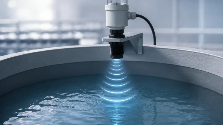
In many industrial applications, flow measurement is only one part of the equation. For example, in a chemical storage and dosing system, the electromagnetic water flow meter measures the rate of chemical injection, while a radar or ultrasonic level sensor monitors the inventory in the supply tank. Ensuring compatibility between these instruments is vital for automated process control.
For engineers looking to integrate high-precision flow data with reliable tank monitoring, it is helpful to consult a manufacturer that understands the full scope of fluid dynamics. You can Review product options and application support on our Main Page to see how our level measurement solutions complement electromagnetic flow technology in complex industrial environments.
Frequently Asked Questions (FAQ)
Can an electromagnetic flow meter measure flow in both directions?
Yes, most modern magmeters are bi-directional. They can be configured to measure flow in both the forward and reverse directions, providing separate totals for each. This is particularly useful in water distribution networks where backflow may occur.
Does the viscosity of the liquid affect the accuracy?
Generally, no. As long as the flow remains laminar or turbulent (and not extremely high-viscosity like paste), the electromagnetic principle is independent of viscosity. However, very high viscosity may affect the flow profile, requiring longer straight pipe runs.
How often should a magmeter be calibrated?
In most municipal water applications, a verification check is recommended annually, with a full wet calibration every 3 to 5 years. In corrosive or abrasive industrial applications, more frequent checks may be necessary to ensure the liner and electrodes remain intact.
What is the difference between an insertion magmeter and a full-bore magmeter?
A full-bore electromagnetic water flow meter replaces a section of the pipe and measures the entire volume of fluid. An insertion magmeter is a probe inserted through a tap in the pipe wall and measures velocity at a single point. Full-bore meters are significantly more accurate, while insertion meters are more cost-effective for very large pipe diameters (DN200 and above).
Conclusion
The electromagnetic water flow meter remains one of the most reliable and maintenance-free technologies for measuring conductive liquids. By carefully selecting liner and electrode materials, adhering to strict installation guidelines—particularly regarding grounding and straight pipe runs—and understanding the conductivity requirements of the media, industrial operators can achieve high-precision flow monitoring for years of service.
For more information on how to pair flow measurement with advanced level sensing technology, visit our Main Page to explore our full range of industrial instrumentation solutions.