Electronic Fluid Level Sensor
Electronic Fluid Level Sensor
In the landscape of modern industrial automation, the electronic fluid level sensor has become an indispensable component for ensuring operational efficiency, safety, and inventory accuracy. Moving beyond traditional mechanical floats and sight glasses, electronic sensors provide real-time data integration, higher precision, and reduced maintenance requirements. These instruments convert physical fluid levels into electrical signals—typically 4-20mA, 0-10V, or digital protocols like Modbus and HART—allowing for seamless monitoring in complex process environments.
As a professional manufacturer, Welk specializes in providing a comprehensive range of these instruments, including radar, ultrasonic, and hydrostatic technologies. Selecting the right electronic fluid level sensor requires a deep understanding of measurement principles, media characteristics, and environmental constraints. This guide provides a technical overview of current technologies to assist engineers in making informed procurement decisions.
Core Measurement Principles
Before selecting a sensor, it is essential to understand how different electronic fluid level sensors interact with the media and the environment. Each principle offers specific advantages depending on the physical properties of the fluid and the vessel.
1. Radar Level Measurement (Non-Contact and Guided)
Radar sensors utilize electromagnetic waves to determine the distance to the fluid surface.
- Non-Contact Radar: These sensors emit high-frequency microwave pulses (often in the 26GHz or 80GHz range). The time-of-flight between emission and reception of the reflected signal is used to calculate the level. This technology is unaffected by temperature, pressure, or vacuum conditions, making it ideal for volatile chemicals and high-temperature oil and gas applications.
- Guided Wave Radar (GWR): GWR uses a probe (cable or rod) to guide the microwave pulse to the liquid surface. This is particularly effective for liquids with low dielectric constants or in applications where foam and turbulence might scatter a non-contact signal.
2. Ultrasonic Level Measurement
Ultrasonic sensors function by emitting high-frequency sound waves. The sensor measures the time it takes for the sound pulse to bounce off the fluid surface and return to the transducer. Because sound speed is influenced by air temperature, these sensors typically include integrated temperature compensation. They are highly cost-effective for water treatment and open-channel flow but may struggle in high-pressure environments or where heavy vapor is present.
3. Hydrostatic Pressure Measurement
This principle relies on the relationship between the height of a liquid column and the pressure it exerts at the base. An electronic fluid level sensor using this method—often called a hydrostatic level transmitter—measures the head pressure. For open tanks, a submersible or flange-mounted pressure sensor is used. For pressurized tanks, differential pressure (DP) transmitters are required to subtract the overhead gas pressure from the total pressure at the bottom.
4. Magnetic Level Gauges with Electronic Transmitters
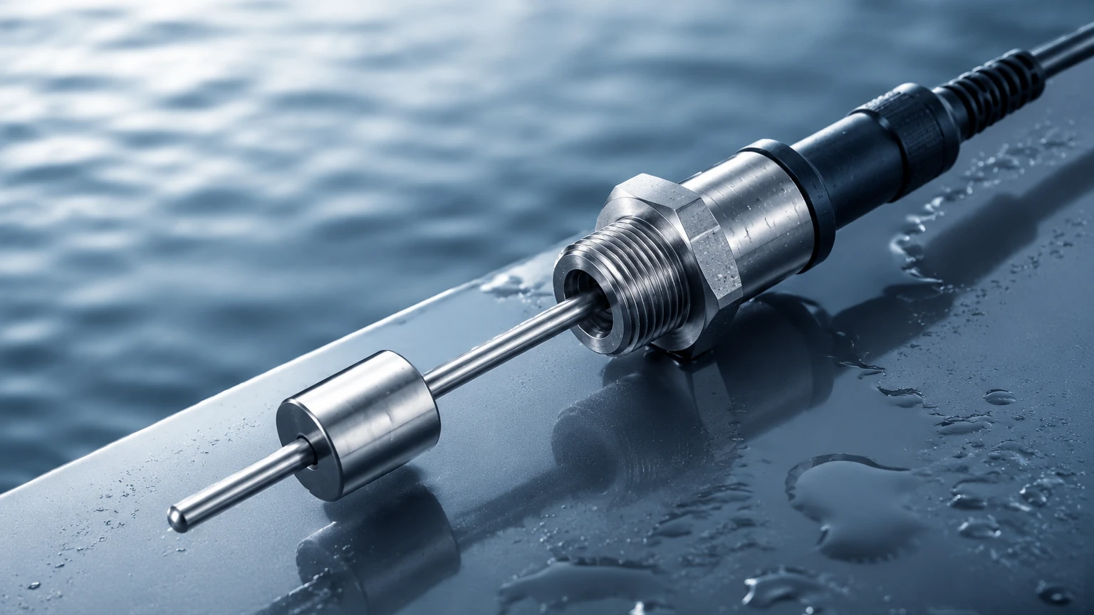
Magnetic level gauges utilize a float containing a permanent magnet that moves with the liquid level inside a bypass chamber. While the visual indication is mechanical, an electronic transmitter (typically a reed chain or magnetostrictive sensor) can be mounted to the outside of the chamber to provide a continuous 4-20mA signal. This provides the reliability of a mechanical system with the data capabilities of an electronic sensor.
Selection Criteria for Electronic Fluid Level Sensors
Choosing the appropriate technology involves balancing accuracy requirements against the physical realities of the installation site. The following table summarizes key selection factors for the most common electronic fluid level sensor types.
| Technology | Accuracy | Media Suitability | Max Temperature | Max Pressure | Best Use Case |
| :— | :— | :— | :— | :— | :— |
| Radar | ±1mm to ±3mm | Corrosive, volatile, viscous | Up to 450°C | Up to 160 bar | Chemical reactors, oil storage |
| Ultrasonic | ±0.25% of range | Water, wastewater, acids | Up to 80°C | Up to 3 bar | Water treatment, sumps |
| Hydrostatic | ±0.1% to ±0.5% | Clean liquids, slurries | Up to 120°C | Dependent on depth | Deep wells, vented tanks |
| Magnetic | ±5mm to ±10mm | High pressure/temp liquids | Up to 400°C | Up to 320 bar | Boilers, interface level |
Application-Specific Engineering
Water and Wastewater Treatment
In water treatment, the primary goal is often cost-effective, reliable monitoring of large volumes. Ultrasonic sensors are the standard choice for sumps and basins due to their non-contact nature, which prevents fouling from raw sewage. However, for deep groundwater wells, hydrostatic submersible transmitters are preferred because they can be lowered hundreds of meters into narrow boreholes.
Chemical and Petrochemical Processing
These environments often involve aggressive media, high pressures, and explosive atmospheres. Radar-based electronic fluid level sensors are preferred here because they are non-mechanical and can be isolated from the process via PTFE or ceramic seals. When dealing with liquid-liquid interfaces (e.g., oil and water), guided wave radar or magnetic level gauges are the most reliable options.
Industrial Automation and OEM
For machine builders, compact size and ease of integration are paramount. Small-form-factor ultrasonic or capacitive sensors are often integrated into coolant tanks or hydraulic reservoirs to provide low-level alerts and automated refill signals. For more detailed product specifications and to explore the full range of available technologies, engineers should consult the Main Page for technical data sheets.
Installation and Configuration Best Practices
Correct installation is as critical as sensor selection. Even the most advanced electronic fluid level sensor will fail if improperly positioned.
1. Avoid Obstructions: For radar and ultrasonic sensors, the "beam angle" must be considered. Ensure the signal path is clear of ladders, agitators, or inflow pipes that could cause false echoes.
2. The Dead Zone (Blocking Distance): Every non-contact sensor has a minimum distance (dead zone) near the transducer face where it cannot measure. Ensure the highest expected fluid level does not enter this zone.
3. Stilling Wells: In tanks with heavy agitation or foam, installing the sensor inside a stilling well (a vertical pipe) can stabilize the fluid surface and provide a much cleaner signal.
4. Cable Shielding: Electronic sensors are susceptible to electromagnetic interference (EMI). Always use shielded cables and ensure proper grounding, especially when sensors are located near large motors or variable frequency drives (VFDs).
5. Venting: For hydrostatic sensors in sealed tanks, ensure the reference capillary in the cable is vented to the atmosphere to compensate for changes in barometric pressure.
Limitations and Common Risks
While electronic fluid level sensors are highly capable, they are not universal solutions. Engineers must be aware of the following risks:
* Media Buildup: In sticky or crystallizing fluids, buildup on an ultrasonic transducer or a radar antenna can attenuate the signal. In such cases, non-contact radar with a flush-mounted antenna or a self-cleaning purge system may be necessary.
* Gas Composition Changes: Ultrasonic sensors rely on a constant speed of sound. If the gas space in a tank changes from air to nitrogen or carbon dioxide, the sensor will report an incorrect level unless recalibrated for the new gas density.
* Specific Gravity Fluctuations: Hydrostatic sensors measure weight, not volume. If the density of the fluid changes due to temperature fluctuations or chemical concentration changes, the level reading will drift. Integrated temperature compensation or secondary density measurement is required for high-precision applications.
Frequently Asked Questions (FAQ)
Q: Can an electronic fluid level sensor measure solids?
A: Yes, but with caveats. Radar and ultrasonic sensors can measure powders and grains, but the "angle of repose" (the slope of the material) can scatter signals. High-power radar is generally the preferred electronic method for solids.
Q: What is the difference between a level switch and a continuous level sensor?
A: A level switch (point level) only detects if the fluid has reached a specific height (on/off). An electronic fluid level sensor (continuous level) provides a constant measurement of the exact level throughout the entire range of the tank.
Q: How often do electronic sensors need calibration?
A: This depends on the technology. Radar and ultrasonic sensors are generally stable for years. Hydrostatic sensors may require annual zero-point checks to account for sensor drift, especially in high-precision or high-temperature applications.
Q: Are these sensors compatible with hazardous areas?
A: Most professional-grade electronic sensors, such as those from Welk, are available with ATEX, IECEx, or UL certifications for use in explosive atmospheres (Class I, Div 1/2).
Conclusion
The transition to electronic fluid level sensors represents a significant upgrade in process control. By understanding the physical principles of radar, ultrasonic, and pressure-based measurement, facilities can reduce downtime and improve accuracy. Whether the application involves corrosive chemicals, wastewater management, or high-pressure steam, there is an electronic solution designed to meet the challenge. For customized OEM/ODM services or to review specific instrument models, please visit the Main Page for comprehensive product support and engineering resources.