Electronic Water Flow Meter
Electronic Water Flow Meter
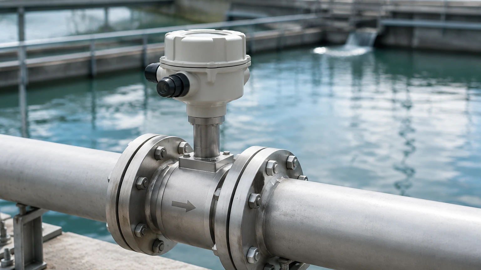
In modern industrial processing and water management, the transition from mechanical registers to electronic water flow meters represents a significant leap in data precision and system integration. Unlike traditional mechanical meters that rely on moving parts like turbines or nutating discs, an electronic water flow meter utilizes advanced sensing technologies—such as electromagnetism, ultrasonics, or vortex shedding—to convert fluid movement into digital signals. This shift eliminates mechanical wear, reduces pressure drop, and enables real-time monitoring essential for automated industrial environments.
For engineers and facility managers, selecting the correct flow measurement technology requires a deep understanding of fluid dynamics and the specific constraints of the application. This guide examines the primary measurement principles, selection criteria, and installation best practices for electronic flow meters in industrial B2B contexts.
Measurement Principles of Electronic Flow Meters
Before selecting a meter, it is critical to understand the physics behind the measurement. Electronic meters are categorized by the method they use to interact with the water flow.
Electromagnetic Flow Meters (Magmeters)
Electromagnetic meters operate based on Faraday’s Law of Electromagnetic Induction. This law states that a conductor (the water) moving through a magnetic field produces an electrical voltage proportional to its velocity.
* The Principle: The meter body contains electromagnetic coils that generate a magnetic field. As conductive water flows through this field, electrodes located on the pipe walls detect the induced voltage. The formula used is $E = kBDv$, where $E$ is the induced voltage, $B$ is the magnetic field strength, $D$ is the distance between electrodes (pipe diameter), and $v$ is the fluid velocity.
* Requirement: The water must have a minimum conductivity, typically $>5$ μS/cm. This makes magmeters ideal for raw water, wastewater, and chemical solutions, but unsuitable for deionized water or hydrocarbons.
Ultrasonic Flow Meters
Ultrasonic technology uses sound waves to determine flow velocity. There are two primary types: Transit-Time and Doppler.
* Transit-Time: This method uses two transducers that function as both transmitters and receivers. They send ultrasonic pulses diagonally across the pipe. The pulse traveling with the flow moves faster than the pulse traveling against it. The time difference ($Δt$) is directly proportional to the flow velocity. This is highly effective for clean water applications.
* Doppler: This method relies on the frequency shift of a sound wave reflected off particles or air bubbles in the water. It is specifically used for "dirty" water or slurries where particles are present to reflect the signal.
Vortex Flow Meters
Vortex meters utilize the Karman Vortex Street principle. When water flows past a bluff body (a non-streamlined object placed in the flow stream), it creates alternating vortices on either side of the body.
* The Principle: The frequency at which these vortices are shed is directly proportional to the flow velocity. An electronic sensor (often a piezoelectric crystal) detects the pressure pulses caused by the vortices and converts them into a digital flow rate. These meters are robust and have no moving parts, making them suitable for high-temperature water and steam applications.
Technical Selection Criteria
Choosing an electronic water flow meter involves balancing performance requirements with fluid characteristics and installation environments. The following table provides a comparison of the most common electronic technologies used in industrial water management.
| Feature | Electromagnetic (Magmeter) | Ultrasonic (Transit-Time) | Vortex Flow Meter |
| :— | :— | :— | :— |
| Fluid Conductivity | Required (>5 μS/cm) | Not Required | Not Required |
| Accuracy | ±0.5% to ±0.2% | ±1.0% to ±0.5% | ±1.0% to ±0.75% |
| Pressure Drop | Zero (Full bore) | Zero (Clamp-on) / Minimal (Inline) | Moderate (Bluff body) |
| Moving Parts | None | None | None |
| Turndown Ratio | 100:1 | 50:1 | 20:1 |
| Typical Applications | Wastewater, Effluent, Raw Water | Cooling Water, DI Water, Large Pipes | High-Temp Water, Condensate |
Fluid Properties and Pipe Conditions
1. Conductivity: If the water is highly purified (deionized), an electromagnetic meter will fail to produce a signal. In such cases, ultrasonic or vortex meters are the standard choice.
2. Solids Content: High concentrations of suspended solids can abrade the liners of magmeters or block the sensors of vortex meters. However, Doppler ultrasonic meters thrive in these conditions.
3. Pipe Material: For ultrasonic clamp-on meters, the pipe material (e.g., carbon steel, PVC, ductile iron) and the presence of internal liners must be known to accurately calculate the sound path.
Installation Considerations
The accuracy of an electronic water flow meter is heavily dependent on the flow profile. Turbulence caused by elbows, valves, or pumps can lead to significant measurement errors.
Straight Pipe Requirements
Most electronic meters require a specific length of straight pipe upstream and downstream of the sensor to ensure a laminar (stable) flow profile.
* Upstream: Typically 10 to 20 times the nominal pipe diameter (10D – 20D).
* Downstream: Typically 5 times the nominal pipe diameter (5D).
If a pump is located immediately before the meter, the upstream requirement may increase to 30D or more. In space-constrained environments, flow conditioners or specific "zero-bore" magmeters may be required.
Orientation and Filling
For accurate measurement, the sensor must always be completely full of water.
* Vertical Installation: Flow should move upward to ensure the pipe remains full and to prevent air bubbles from being trapped at the sensor head.
* Horizontal Installation: The electrodes (in magmeters) should be positioned at the 3 o'clock and 9 o'clock positions. Placing them at the top (12 o'clock) risks interference from air pockets, while the bottom (6 o'clock) risks interference from sediment buildup.
Grounding and Interference
Electromagnetic meters are sensitive to stray electrical currents in the piping system. Proper grounding is essential, especially in plastic or lined pipes. Grounding rings are often used to provide a stable electrical reference point between the fluid and the meter electronics. Additionally, signal cables should be shielded and separated from high-voltage power lines to prevent electromagnetic interference (EMI).
Integration with Level Measurement Systems
In comprehensive industrial automation, flow measurement is rarely an isolated data point. It is frequently integrated with level measurement technologies to provide a full picture of process efficiency. For example, in a water treatment plant, ultrasonic level sensors monitor the height of water in a basin while an electronic flow meter monitors the effluent discharge rate.
This synergy allows for:
* Mass Balance Calculations: Comparing the volume entering a tank (flow) vs. the change in stored volume (level).
* Leak Detection: Identifying discrepancies between level drop and expected flow rates.
* Pump Control: Using level setpoints to trigger pumps, while flow meters verify that the pumps are operating at their rated capacity.
For organizations looking to optimize these integrated systems, consulting a manufacturer that understands both level and flow dynamics is beneficial. You can Review product options and application support to see how various industrial instruments work in tandem.
Common Risks and Limitations
While electronic meters are superior to mechanical ones in many ways, they are not without limitations:
1. Scaling and Coating: In hard water applications, calcium carbonate or other minerals can build up on the electrodes of a magmeter or the transducers of an ultrasonic meter. This "insulates" the sensor and degrades accuracy. Periodic cleaning or the use of non-stick liners (like PTFE) is necessary.
2. Signal Attenuation: In ultrasonic systems, high concentrations of entrained air or bubbles can scatter the sound waves, leading to a "signal loss" error.
3. Power Dependency: Unlike mechanical meters, electronic meters require a stable power supply (typically 24V DC or 110/220V AC). In remote locations, this may necessitate solar power or high-capacity battery packs.
4. Initial Cost: The upfront investment for an electronic water flow meter is generally higher than a mechanical meter. However, the Total Cost of Ownership (TCO) is often lower due to reduced maintenance and longer service life.
Maintenance and Calibration
To maintain B2B quality standards and regulatory compliance, electronic meters should undergo periodic verification.
* In-situ Verification: Many modern electronic meters feature internal diagnostics that check the health of the coils, electrodes, and transmitter circuitry without removing the meter from the line.
* Wet Calibration: For high-precision applications, the meter should be removed and tested against a master meter or a gravimetric weigh scale every 1–3 years.
* Zero-Point Adjustment: Upon installation, a "zero-check" should be performed under no-flow conditions (with the pipe full) to ensure the electronics are correctly calibrated to the specific environment.
Frequently Asked Questions (FAQs)
Q: Can an electronic water flow meter measure flow in both directions?
A: Yes, most electromagnetic and ultrasonic meters are inherently bi-directional. They can track both forward and reverse flow and provide separate totals for each, which is useful in complex distribution networks.
Q: How do I handle flow measurement in partially filled pipes?
A: Standard electronic meters require a full pipe. If the pipe is partially filled (like a gravity-fed sewer), you must use a specialized "partially filled pipe" magmeter which includes additional electrodes at different heights, or use an area-velocity method combining an ultrasonic level sensor with a submerged flow transducer.
Q: What is the impact of water temperature on accuracy?
A: Electronic meters are generally more stable than mechanical ones regarding temperature. However, extreme temperatures can change the density and viscosity of water. High-end transmitters include temperature compensation algorithms to maintain accuracy across a wide thermal range.
Q: Is it possible to install an electronic meter without cutting the pipe?
A: Yes, clamp-on ultrasonic flow meters allow for non-invasive installation. Transducers are strapped to the outside of the pipe, making them ideal for retrofitting or for applications where process downtime must be avoided.
By understanding these technical nuances, engineers can ensure that their electronic water flow meter provides reliable data for years, supporting better resource management and operational efficiency in industrial processes.