How Does a Vortex Flow Meter Work
How Does a Vortex Flow Meter Work
In the landscape of industrial process control, the ability to measure the flow rate of liquids, gases, and steam accurately is fundamental to operational efficiency and safety. Among the various technologies available, the vortex flow meter has emerged as a preferred choice for many engineers due to its lack of moving parts and its versatility across different media. Understanding how does a vortex flow meter work requires a dive into fluid dynamics, specifically a phenomenon known as the Von Kármán effect.
This guide explores the underlying physics, the mechanical components, and the practical application criteria essential for selecting and installing these instruments in industrial environments.
The Fundamental Principle: The Von Kármán Effect
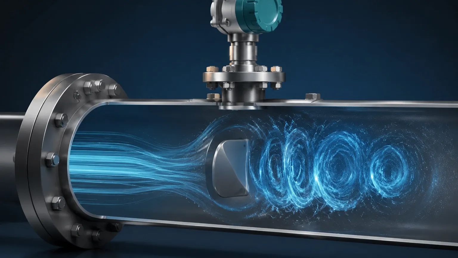
The operation of a vortex flow meter is based on the principle of vortex shedding. When a fluid (liquid, gas, or steam) flows past a non-streamlined object, often referred to as a "bluff body" or "shedder bar," it cannot follow the sharp contours of the object. As the fluid passes the bluff body, it separates from the surface, creating localized areas of high and low pressure.
This separation results in the formation of alternating vortices (eddies) on either side of the bluff body. These vortices trail behind the object in two parallel rows, a pattern known as the Von Kármán vortex street.
The Mathematical Relationship
The frequency at which these vortices are shed is directly proportional to the velocity of the fluid. This relationship is defined by the Strouhal equation:
f = St × (V / d)
Where:
* f is the frequency of vortex shedding (Hz).
* St is the Strouhal number (a dimensionless constant specific to the shape of the bluff body).
* V is the velocity of the fluid (m/s).
* d is the width of the bluff body (m).
Because the width of the shedder bar and the Strouhal number remain constant over a wide range of Reynolds numbers, the frequency of the vortices provides a linear and highly accurate measurement of the fluid velocity. By multiplying this velocity by the cross-sectional area of the pipe, the meter calculates the volumetric flow rate.
Key Components of a Vortex Flow Meter
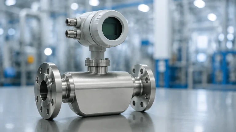
A vortex flow meter consists of three primary elements that work in tandem to convert fluid motion into a readable electronic signal.
1. The Bluff Body (Shedder Bar)
This is a solid, stationary component placed vertically across the flow stream. Its shape is critical; it must be designed to generate strong, detectable vortices while minimizing permanent pressure loss. Most modern meters use a triangular or trapezoidal cross-section.
2. The Sensor
To measure the frequency of the vortices, a sensor is positioned either inside or immediately behind the bluff body. The most common type is a piezoelectric sensor. As each vortex passes, it creates a small pressure fluctuation. The piezoelectric crystal detects these mechanical stresses and converts them into low-voltage electrical pulses. Other sensing methods include ultrasonic sensors (which detect the shift in a beam's phase) or thermal sensors, though piezoelectric is the industry standard for its durability.
3. The Transmitter
The transmitter receives the raw pulses from the sensor. It filters out background noise (such as pipe vibration), calculates the flow rate based on the pre-programmed pipe dimensions and Strouhal number, and outputs a standardized signal—typically 4-20mA, pulse, or digital protocols like HART or Modbus.
Practical Selection Criteria
When evaluating flow measurement solutions, it is important to match the technology to the specific process conditions. For comprehensive level and flow instrumentation options, engineers often consult the Main Page of specialized manufacturers to compare vortex technology against ultrasonic or electromagnetic alternatives.
Fluid Compatibility Table
| Fluid Type | Suitability | Considerations |
| :— | :— | :— |
| Saturated Steam | Excellent | Primary choice for steam due to high temperature tolerance. |
| Superheated Steam | Excellent | Requires pressure and temperature compensation for mass flow. |
| Clean Liquids | Good | Low viscosity liquids work best; avoid slurries. |
| Gases (Air, N2, CO2) | Excellent | High sensitivity required for low-density gases. |
| High Viscosity Liquids | Poor | High viscosity dampens vortex formation; Re must be > 20,000. |
| Corrosive Media | Good | Requires compatible wetted materials (e.g., Stainless Steel, Hastelloy). |
Installation Considerations
The accuracy of a vortex flow meter is highly dependent on the flow profile of the fluid as it enters the device. If the flow is turbulent or distorted by upstream piping, the vortex shedding will be inconsistent.
1. Straight Pipe Runs: To ensure a fully developed flow profile, standard installations require a minimum of 10 to 20 diameters (D) of straight pipe upstream and 5 diameters (D) downstream. If a valve or a double elbow is present upstream, the required straight run may increase to 30D or more.
2. Orientation: Vortex meters can typically be installed in horizontal, vertical, or inclined positions. However, for liquid applications, the pipe must remain completely full. In vertical lines, the flow should always be upward to prevent air pockets.
3. Vibration: Since sensors detect pressure pulses, excessive mechanical vibration in the piping can introduce "noise" that the transmitter might mistake for flow. It is advisable to support the piping near the meter or use meters with advanced digital signal processing (DSP) to filter out vibration frequencies.
4. Insulation: When measuring steam or high-temperature fluids, the transmitter electronics should be protected from heat. Many meters feature an extended neck to move the electronics away from the hot pipe, and insulation should only cover the pipe and the meter body, leaving the transmitter head exposed to ambient air.
Limitations and Common Risks
While robust, vortex flow meters are not universal solutions. Engineers must be aware of the following limitations:
* The Reynolds Number Constraint: Vortex shedding only becomes stable and linear above a certain Reynolds number (typically Re > 10,000 to 20,000). At very low flow velocities or high viscosities, the vortices cease to form, and the meter will read zero even if there is movement.
* Pressure Drop: The bluff body acts as an obstruction in the pipe, causing a permanent pressure drop. While usually lower than that of an orifice plate, it must be accounted for in system head-loss calculations.
* Cavitation: In liquid applications, if the pressure drops too low as the fluid accelerates around the bluff body, vapor bubbles may form (cavitation). This can damage the sensor and lead to significant measurement errors. Always ensure the process pressure is high enough to prevent boiling.
Frequently Asked Questions (FAQs)
1. Can a vortex flow meter measure mass flow?
A standard vortex meter measures volumetric flow. However, "multivariable" vortex meters are available that include built-in temperature and pressure sensors. Using these inputs and the known density tables of the fluid, the transmitter can calculate the real-time mass flow, which is particularly useful for steam and compressed gases.
2. What happens if the fluid is dirty or contains solids?
Vortex meters are intended for clean or slightly dirty fluids. Large solids can impact the bluff body or damage the sensor. If the fluid contains significant particulates, a magnetic flow meter or a robust ultrasonic meter might be more appropriate.
3. Does the meter require periodic recalibration?
Because the Strouhal number is based on the physical geometry of the bluff body (which does not change), vortex meters are highly stable over time. Recalibration is usually only necessary if the bluff body becomes eroded or coated with scale, which would change its effective width.
4. How does it compare to an orifice plate?
Vortex meters offer a much wider rangeability (turndown ratio)—typically 10:1 to 30:1—compared to the 3:1 or 4:1 typical of orifice plates. They also have lower maintenance requirements since there are no impulse lines to clog or freeze.
Conclusion
How does a vortex flow meter work? It leverages the predictable nature of fluid dynamics to provide a reliable, low-maintenance measurement solution. By understanding the Von Kármán effect and adhering to strict installation guidelines regarding straight pipe runs and Reynolds numbers, industrial operators can achieve precise flow monitoring for steam, gas, and liquid processes. For those integrating these sensors into broader automation systems, reviewing the technical specifications on the Main Page ensures that the selected instrument meets the specific pressure, temperature, and material requirements of the application.