Endress-hauser
Endress-hauser
In the field of industrial process automation, Endress+Hauser is recognized as a global leader in providing comprehensive measurement instrumentation. For engineers and procurement specialists, understanding the technical landscape established by such industry benchmarks is essential for selecting the right level measurement solutions. This guide examines the core technologies associated with high-end process instrumentation, focusing on the principles of operation, application suitability, and the practical considerations required to ensure accurate level monitoring in demanding industrial environments.
Selecting a level transmitter—whether from a global conglomerate or a specialized manufacturer like Welk—requires a deep understanding of the physics of the media and the constraints of the vessel. By evaluating the technological standards set by companies like Endress+Hauser, users can better navigate the options available on the Main Page of modern instrumentation catalogs.
Core Measurement Principles in Industrial Level Sensing
Before selecting a specific instrument, it is critical to understand the underlying physical principles that govern level measurement. Most industrial applications rely on one of three primary methods: Time-of-Flight (ToF), Hydrostatic Pressure, or Electromechanical interaction.
Time-of-Flight (ToF) Technology
ToF is the foundation for both radar and ultrasonic measurement. The instrument emits a signal (either an electromagnetic wave or a sound pulse) that travels to the product surface, reflects, and returns to the sensor. The distance is calculated using the formula:
*Distance = (Speed of Signal × Time Delay) / 2*.
* Radar (Microwave): Radar level meters use high-frequency electromagnetic waves. These waves are largely unaffected by air temperature, pressure, or vacuum. Radar is further divided into Non-contact (Free-space) and Guided Wave Radar (GWR).
* Ultrasonic: These sensors use mechanical sound waves. Because the speed of sound is dependent on the medium (usually air), ultrasonic sensors are sensitive to temperature fluctuations and heavy vapor, making them more suitable for stable liquid environments or open-channel flow measurement.
Hydrostatic Pressure
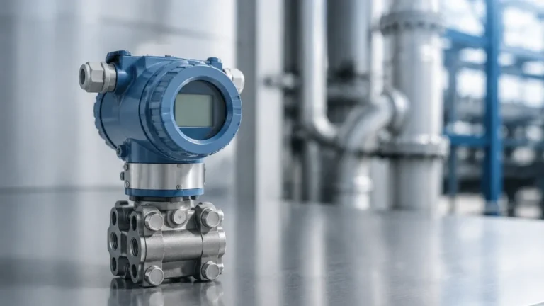
This principle relies on the relationship between the height of a liquid and the pressure it exerts at the bottom of a vessel. The calculation is defined by:
*P = ρ × g × h*
Where *P* is pressure, *ρ* (rho) is the density of the liquid, *g* is gravity, and *h* is the height. Hydrostatic transmitters are favored for their simplicity and reliability in vented or pressurized tanks where the liquid density remains constant.
Capacitance and Conductivity
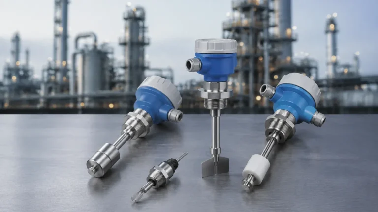
These principles are typically used for point level detection (switches). Capacitance sensors detect changes in the electrical field between two electrodes as the media rises, while conductive sensors rely on the medium's ability to complete an electrical circuit.
Evaluation of Radar Level Technology: Micropilot and Levelflex Standards
Endress+Hauser’s Micropilot (non-contact radar) and Levelflex (guided wave radar) series have set high benchmarks for the industry. When evaluating these or equivalent instruments from Welk, engineers must consider the frequency and the dielectric constant (εr) of the material.
Non-Contact Radar (Free-space)
Modern radar instruments often operate at frequencies such as 26 GHz or 80 GHz. Higher frequencies allow for smaller antenna sizes and narrower beam angles. A narrow beam is essential in tanks with internal obstructions (like agitators or heating coils) because it reduces the risk of false echoes.
* Application Note: For liquids with low dielectric constants (e.g., hydrocarbons), the reflection signal is weak. In these cases, high-sensitivity electronics or Guided Wave Radar are required.
Guided Wave Radar (GWR)
In GWR systems, the microwave pulse is conducted along a probe (rod or cable). This focuses the energy and eliminates the signal spread associated with free-space radar. GWR is particularly effective for:
1. Interface Measurement: Measuring the level of two different liquids (e.g., oil over water).
2. Foaming Surfaces: Where free-space radar signals might be absorbed or scattered.
3. Low Dielectric Media: Where the probe ensures the signal reaches the surface and returns with sufficient strength.
Selection Criteria for Process Industry Applications
Choosing the correct instrument involves matching the process conditions with the sensor's physical limits. The following table provides a general selection guide based on common industrial parameters.
| Process Condition | Recommended Technology | Limitation/Consideration |
| :— | :— | :— |
| High Temperature (>250°C) | Radar or Magnetic Level Gauge | Requires specialized cooling fins or high-temp gaskets. |
| Corrosive Acids | PTFE-coated Ultrasonic or Radar | Ensure all wetted parts are chemically compatible. |
| Heavy Dust/Solids | 80 GHz Radar | High frequency penetrates dust better than ultrasonic. |
| Vacuum Conditions | Radar or Hydrostatic | Ultrasonic cannot function in a vacuum (no medium for sound). |
| Interface (Oil/Water) | Guided Wave Radar (GWR) | Requires a significant difference in dielectric constants. |
| Small Tanks (<2m) | Ultrasonic or Hydrostatic | Check the "dead zone" or blocking distance of the sensor. |
The Importance of Dielectric Constant (DC)
For all radar-based measurements, the dielectric constant of the medium is the most critical factor. Materials with a DC below 1.9 (like liquefied gases) are difficult to measure with standard non-contact radar. In these instances, a stilling well or a GWR probe must be used to concentrate the signal.
Installation and Engineering Considerations
Even the most advanced Endress+Hauser or Welk transmitter will fail if installed incorrectly. Engineering teams should adhere to the following checklists during the design phase.
1. The Blocking Distance (Dead Zone)
Every sensor has a range near the antenna or transducer where measurement is impossible. This is known as the blocking distance. If the liquid level enters this zone, the device may report a "full" error or a frozen reading. Ensure the mounting nozzle height accounts for this distance.
2. Nozzle Geometry
The mounting nozzle should be as short and wide as possible. If a nozzle is too long or narrow, it can create internal reflections (ringing) that interfere with the surface signal. For 80 GHz radars, this is less of a concern due to the narrow beam, but for lower frequency devices, it is a common failure point.
3. Obstruction Avoidance
Radar and ultrasonic beams spread as they travel. The "beam diameter" at the bottom of the tank can be calculated using the beam angle provided in the technical datasheet. Ensure that no ladders, pipes, or agitator blades intersect the beam path. If obstructions are unavoidable, most modern transmitters offer "false echo suppression" software to map out and ignore these static reflections.
4. Pressure and Temperature Limits
Standard sensors are often rated for -40°C to +80°C. For steam-jacketed vessels or cryogenic storage, specialized process connections and thermal decouplers are mandatory. Always verify the flange rating (e.g., ANSI 150lb or PN16) against the maximum possible vessel pressure.

Common Risks and Mitigation Strategies
In B2B process environments, downtime is the primary risk. When integrating level measurement systems, consider the following:
* Build-up and Fouling: In wastewater or slurry applications, material can build up on the sensor face. While some radar units can "see through" thin films, heavy build-up will eventually cause signal loss. Choosing a flush-mounted antenna or a non-contact solution over a probe-based solution can mitigate this.
* Turbulence: Rapidly moving surfaces in mixing tanks can scatter radar signals. Using a stilling well—a vertical pipe that acts as a calm chamber for the liquid—is the standard engineering solution for turbulent environments.
* Signal Compatibility: Ensure the transmitter output (4-20mA HART, Profibus, or Modbus) is compatible with the existing PLC or DCS architecture. Modern facilities are increasingly moving toward digital protocols for remote diagnostics.
Information Confirmation Before Procurement
Before finalizing a purchase from a provider or reviewing options on the Welk Main Page, the project audience should confirm the following data points:
1. Media Characteristics: Exact dielectric constant, density, and chemical composition.
2. Vessel Dimensions: Total height, diameter, and the presence of any internal structures.
3. Process Dynamics: Maximum rate of level change (m/min) to ensure the sensor's sampling rate can keep up.
4. Environmental Hazards: Is the area classified as explosive (ATEX/Ex-rated)? If so, intrinsically safe or explosion-proof housings are required.
Frequently Asked Questions (FAQ)
Q: Can radar level meters measure through plastic tank walls?
A: Yes, non-contact radar can often measure through the top of plastic (polyethylene or polypropylene) tanks without a process opening, provided the plastic is not conductive and the signal loss is accounted for.
Q: What is the difference between 26 GHz and 80 GHz radar?
A: 80 GHz radar has a much narrower beam and a smaller antenna. It is better for small nozzles and avoiding obstructions. 26 GHz is often more robust in applications with heavy steam or condensation.
Q: Why is my ultrasonic sensor giving erratic readings at noon?
A: This is often due to temperature shifts. If the sensor is in direct sunlight, the air temperature inside the tank changes, which changes the speed of sound. Ensure the sensor has an internal or external temperature compensator and a sunshade.
Q: When should I choose a hydrostatic transmitter over a radar?
A: Hydrostatic transmitters are excellent for deep wells, vented water tanks, and applications where the top of the tank is inaccessible. They are generally more cost-effective but require the liquid density to remain stable for accurate height calculation.
By following these engineering principles and understanding the technical standards established by industry leaders like Endress+Hauser, organizations can implement reliable level measurement strategies that minimize maintenance and maximize process efficiency.