Float Level Monitoring
Float Level Monitoring
Float level monitoring remains one of the most reliable and widely implemented methods for liquid level detection in industrial environments. Based on the fundamental physics of buoyancy, these systems provide a direct, mechanical response to changes in fluid levels, making them indispensable for applications ranging from simple sump pump control to complex chemical processing. For engineers and facility managers, understanding the nuances of float-based technology is essential for ensuring process safety and operational efficiency.
As a professional manufacturer of industrial level measurement instruments, Welk provides a range of solutions designed to meet the rigorous demands of modern industry. Whether the application requires a simple point-level alarm or high-precision continuous data, selecting the right approach to float level monitoring is the first step toward a stable automated system.
Measurement Principles of Float Systems
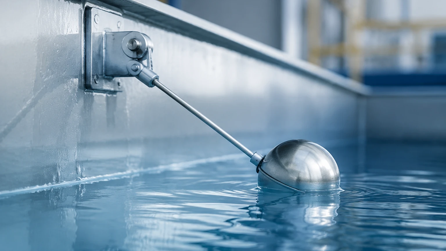
All float level monitoring systems operate on Archimedes' Principle, which states that any object, wholly or partially immersed in a fluid, is buoyed up by a force equal to the weight of the fluid displaced by the object. In practical level measurement, a float is designed with a lower density than the process liquid, allowing it to move vertically as the liquid level rises or falls.
Point Level Detection (Float Switches)
In a basic float switch, the float contains an internal magnet. As the liquid level moves the float toward a specific set point, the magnetic field actuates a reed switch or a microswitch located within a stationary stem or housing. This creates a discrete electrical signal (on/off) used to trigger alarms, start pumps, or open valves. These are typically used for high-level overflow protection or low-level dry-run prevention.
Continuous Level Measurement
For continuous float level monitoring, two primary methods are utilized:
1. Resistance Chain (Reed Chain): The stem contains a series of reed switches and resistors. As the magnetic float moves, it closes specific switches, altering the total resistance of the circuit. This resistance change is converted into a 4-20mA or digital signal proportional to the level.
2. Magnetostrictive Technology: This is a high-precision method. A sonic pulse is sent down a magnetostrictive wire inside the probe. When this pulse meets the magnetic field of the float, a torsional strain wave is generated and travels back to the electronics. By measuring the time-of-flight of this wave, the system determines the float's position with sub-millimeter accuracy.
Types of Float Monitoring Instruments
Choosing the correct instrument depends on whether the goal is simple automation or detailed process tracking. For comprehensive options, engineers often consult the Main Page of specialized manufacturers to compare technical specifications.
Magnetic Level Gauges
Magnetic level gauges are used for visual bypass monitoring. A float resides inside a chamber connected to the side of a tank. As the float moves, it flips magnetic flags or rollers on an external scale. This provides a clear, high-visibility local indication without requiring power, while also allowing for the attachment of transmitters for remote monitoring.
Float Level Transmitters
These are top-mounted probes that provide a continuous signal. They are ideal for deep tanks where visual side-mounting is not feasible. Modern transmitters often feature HART, Modbus, or Profibus protocols to integrate directly into a facility's PLC or SCADA system.
Cable-Suspended Float Switches
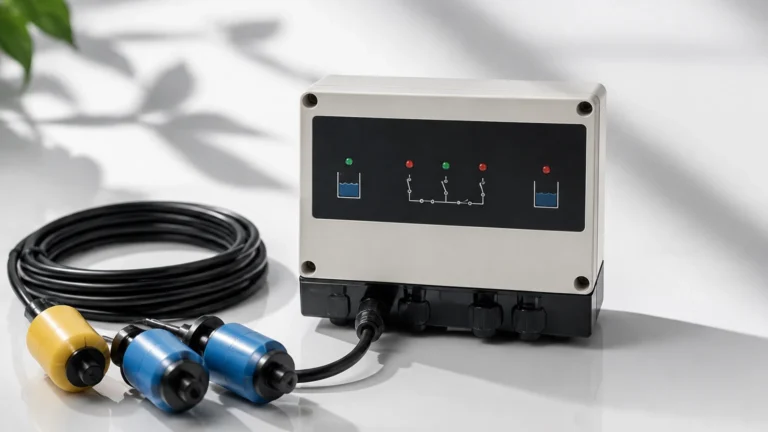
Used primarily in water treatment and sewage applications, these floats are suspended by their own electrical cable. When the liquid level reaches the float, it tilts, moving an internal ball-actuated switch. These are robust and highly resistant to fouling in wastewater.
Practical Selection Criteria
Selecting a float system requires a detailed analysis of the process media and the vessel environment. The following table provides a comparison of common float monitoring technologies.
Technology Selection Table
| Feature | Float Switch (Point) | Reed Chain Transmitter | Magnetostrictive Transmitter | Magnetic Level Gauge |
| :— | :— | :— | :— | :— |
| Measurement Type | Discrete (On/Off) | Continuous | Continuous (High Precision) | Visual + Continuous |
| Accuracy | ± 2-5 mm | ± 5-10 mm | ± 0.1-1 mm | ± 5-10 mm |
| Max Temperature | Up to 200°C | Up to 150°C | Up to 250°C | Up to 400°C |
| Max Pressure | Up to 40 bar | Up to 40 bar | Up to 100 bar | Up to 200 bar |
| Typical Media | Water, Oils, Chemicals | Clean Liquids | Fuels, Solvents, Chemicals | High Pressure/Temp Fluids |
| Maintenance | Low | Low | Very Low | Moderate (Cleaning) |
Material Compatibility
The float and stem must be chemically compatible with the liquid. Common materials include:
* 304/316L Stainless Steel: Standard for water, food processing, and general industrial chemicals.
* PP (Polypropylene): Suitable for acidic or alkaline solutions at lower temperatures.
* PVDF/PTFE: Used for highly aggressive corrosive media.
* Titanium: Reserved for specialized high-strength, high-corrosion applications.
Installation Considerations
To ensure the longevity and accuracy of float level monitoring systems, several installation factors must be addressed:
1. Vertical Alignment: Most float transmitters must be installed perfectly vertical (within ±5°) to prevent the float from binding or sticking against the stem.
2. Stilling Wells: In tanks with high turbulence, such as those with agitators or high-velocity inlets, a stilling well (a perforated pipe) should be used. This protects the float from lateral forces and ensures a stable liquid surface for measurement.
3. Proximity to Magnetic Fields: Since many float systems rely on magnetic coupling, they should be installed away from large motors, transformers, or other sources of high electromagnetic interference.
4. Clearance: Ensure there is sufficient overhead clearance for the installation and removal of long probe stems. In some cases, flexible probes are used for very deep tanks where rigid stems are impractical.
Limitations and Risks
While float level monitoring is highly reliable, it is not a "one-size-fits-all" solution. Engineers should be aware of the following limitations:
* Coating and Buildup: If the process liquid is highly viscous or prone to crystallization, material can build up on the stem or the float. This increases the weight of the float (changing its buoyancy) or causes it to stick in one position.
* Specific Gravity Changes: Because floats rely on buoyancy, they are calibrated for a specific liquid density. If the process involves fluids with significantly varying densities (e.g., mixing different chemicals), the float may sit higher or lower in the liquid, leading to measurement errors.
* Mechanical Wear: As a contact-based technology, the moving parts are subject to mechanical wear over millions of cycles, particularly in high-vibration environments.
* Solid Content: Large solids or debris in the liquid can physically obstruct the float's movement. For slurries, non-contact methods like radar or ultrasonic sensors are often preferred.
Frequently Asked Questions (FAQ)
Q: Can float level monitoring be used for interface measurement?
A: Yes. By using a float weighted to a specific density between two immiscible liquids (e.g., oil and water), the float will sink through the upper layer and float on the lower layer, effectively monitoring the interface level.
Q: How do I handle foaming in the tank?
A: Float systems are generally excellent for foam applications. Unlike ultrasonic or radar sensors, which may be confused by foam surfaces, a mechanical float will pass through the foam and sit on the actual liquid surface.
Q: What is the maximum length for a float transmitter?
A: Rigid stems typically reach up to 4 or 6 meters. For deeper applications, flexible magnetostrictive probes can extend up to 15-20 meters.
Q: Do float switches require regular calibration?
A: Generally, no. Since they are mechanical/magnetic devices, the set point is fixed by the physical position of the switch. However, periodic cleaning and functional testing (tripping the switch manually) are recommended as part of routine maintenance.
Conclusion and Next Steps
Float level monitoring remains a primary choice for industrial automation due to its simplicity, reliability, and cost-effectiveness. By understanding the specific gravity of the media, the pressure/temperature requirements, and the physical constraints of the tank, engineers can implement a system that provides years of trouble-free service.
For those designing new systems or upgrading existing infrastructure, it is critical to confirm the chemical compatibility and electrical requirements of the chosen instrument. Reviewing the available configurations on the Main Page of a dedicated manufacturer like Welk ensures that the selected technology aligns with both the technical demands and the safety standards of the specific industrial application.