Fuel Tank Measurement Device
Fuel Tank Measurement Device
In industrial operations ranging from power generation to petrochemical logistics, the accuracy of a fuel tank measurement device is a critical factor in both operational efficiency and safety. Managing fuel inventory requires more than just a simple volume check; it involves understanding the physical properties of the medium, the geometry of the storage vessel, and the environmental conditions that can affect sensor performance.
Professional manufacturers like Welk provide a range of technologies designed to address these complexities. Whether dealing with diesel, heavy fuel oil (HFO), or volatile gasoline, selecting the correct instrumentation is the first step toward achieving reliable automation and inventory control. This article explores the core measurement principles, selection criteria, and installation best practices for industrial fuel level monitoring.
Fundamental Measurement Principles for Fuel Systems
Before selecting a fuel tank measurement device, it is essential to understand the underlying physics of the different technologies available. Most industrial fuel level sensors fall into one of four categories: radar, ultrasonic, hydrostatic, or magnetic.
Radar Level Measurement (ToF)
Radar level meters utilize Time of Flight (ToF) technology. The device emits high-frequency electromagnetic pulses that travel at the speed of light. When these pulses hit the fuel surface, they are reflected back to the sensor. The distance is calculated based on the time interval between emission and reception.
In fuel applications, radar is often preferred because electromagnetic waves are not affected by air temperature, pressure, or the presence of vapors. However, the dielectric constant ($ε_r$) of the fuel is a significant factor. Most fuels have a low dielectric constant (typically between 1.9 and 2.2), which means they reflect less energy than water. High-frequency radar (such as 80GHz) is often recommended for these applications because it offers a more focused beam and better signal processing to handle weak reflections.
Ultrasonic Level Measurement
Ultrasonic sensors work on a similar ToF principle but use sound waves instead of electromagnetic waves. A transducer emits an ultrasonic pulse that reflects off the liquid surface. Because sound speed is influenced by air temperature, these devices include integrated temperature sensors to compensate for changes in the vapor space. While cost-effective, ultrasonic devices may struggle in fuel tanks where heavy vapors or high pressure can alter the speed of sound, leading to measurement errors.
Hydrostatic Level Measurement
Hydrostatic transmitters measure the pressure exerted by the liquid column at the bottom of the tank. The relationship is defined by the formula $P = ρgh$, where $P$ is pressure, $ρ$ is the density of the fuel, $g$ is gravity, and $h$ is the height of the liquid. This method is highly reliable for vented tanks. However, because fuel density changes with temperature, hydrostatic systems often require density compensation to maintain high accuracy over varying seasonal temperatures.
Magnetic Level Gauges
Magnetic level gauges are used for visual indication and remote signaling. They consist of a bypass chamber connected to the tank. Inside the chamber, a float containing a permanent magnet moves with the fuel level. Outside the chamber, a series of magnetic flaps or a transmitter detects the position of the float. This technology is robust and provides a clear physical backup to electronic systems.
Comparing Technologies for Fuel Tank Measurement
Each technology offers specific advantages depending on the tank size and the type of fuel being stored. The following table provides a comparison of common technologies used in industrial fuel monitoring.
| Technology | Accuracy | Best For | Limitations |
| :— | :— | :— | :— |
| 80GHz Radar | ±1 mm | Large storage tanks, low $ε_r$ fuels | Higher initial cost |
| Guided Wave Radar | ±2 mm | Small tanks, foaming liquids | Contacting method; probe buildup |
| Ultrasonic | ±0.25% of range | Diesel, non-volatile liquids | Affected by heavy vapors and wind |
| Hydrostatic | ±0.1% to 0.5% | Underground tanks, vented vessels | Requires constant density |
| Magnetic Gauge | ±5 mm to 10 mm | High-pressure process tanks | Moving parts; float maintenance |
For a detailed look at specific sensor models and their technical data sheets, you can visit the Main Page of the manufacturer's catalog.
Selection Criteria for Industrial Fuel Monitoring
Choosing the right fuel tank measurement device requires a thorough evaluation of the application environment. Engineers should confirm the following parameters before procurement:
1. Fuel Characteristics
The chemical composition of the fuel dictates the material compatibility of the sensor. For example, biofuels or additives may require specific stainless steel grades (e.g., 316L) or PTFE coatings. Additionally, the dielectric constant of the fuel must be high enough for the radar or capacitance sensor to detect the surface accurately.
2. Tank Geometry and Obstructions
The presence of internal structures such as heating coils, ladders, or agitators can interfere with non-contact sensors. In tanks with complex internals, a narrow-beam 80GHz radar or a Guided Wave Radar (GWR) with a coaxial probe is often the best solution to avoid false echoes.
3. Temperature and Pressure
Standard fuel storage usually occurs at atmospheric pressure, but process tanks in refineries or power plants may operate at elevated temperatures or pressures. Hydrostatic and magnetic gauges must be rated for the maximum design pressure of the vessel. For high-temperature heavy fuel oils, sensors must be able to withstand the heat without compromising the electronics.
4. Accuracy and Regulatory Requirements
For custody transfer (where fuel is being bought or sold based on the measurement), extremely high accuracy (e.g., ±1 mm or better) is required. For simple inventory monitoring or dry-run protection for pumps, a lower accuracy ultrasonic or hydrostatic sensor may be sufficient.
Installation Guidelines and Best Practices
Even the most advanced fuel tank measurement device will fail if installed incorrectly. Proper positioning is the key to long-term reliability.
* Avoid the Filling Stream: Never install a level sensor directly in the path of the incoming fuel flow. Turbulence and splashing will cause signal instability and may damage the probe.
* Nozzle Dimensions: For radar and ultrasonic sensors, the height and diameter of the mounting nozzle must be considered. If the nozzle is too long and narrow, it can create "ringing" or parasitic reflections that mask the actual fuel level.
* Dead Zones: Every sensor has a "dead zone" or "blocking distance" near the transducer face where measurement is impossible. Ensure the sensor is mounted high enough so that the maximum fuel level does not enter this zone.
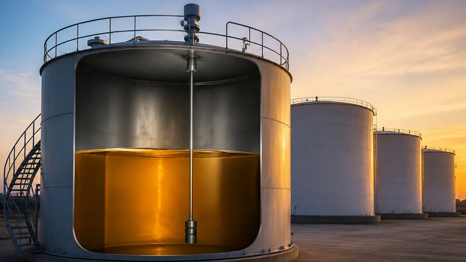
* Still-pipes and Bypass Chambers: In tanks with significant turbulence or foam, installing the sensor inside a still-pipe (a vertical pipe with vent holes) can stabilize the liquid surface and provide a much cleaner signal for radar and ultrasonic devices.
* Grounding: In fuel applications, static electricity is a major safety concern. Ensure all electronic instruments are properly grounded and meet the required explosion-proof (Ex) ratings for the zone, such as ATEX or IECEx standards.
Technical Limitations and Environmental Factors
While modern instrumentation is highly capable, there are inherent limitations to consider:
1. Vapor and Condensation: Fuel vapors can condense on the face of an ultrasonic transducer, dampening the signal. Radar is generally immune to this, but heavy buildup of viscous fuels (like crude or HFO) on a radar antenna can still attenuate the signal. Self-cleaning antenna designs or air purging systems can mitigate this.
2. Foaming: Some diesel fuels can foam during high-speed filling. Ultrasonic waves are often absorbed by foam, leading to a "loss of echo." Radar can typically penetrate light foam, but Guided Wave Radar is the most reliable choice for heavy foaming applications.
3. Density Fluctuations: If using hydrostatic pressure sensors, a change in fuel temperature from 10°C to 40°C can change the density enough to cause a 2-3% error in level reading if not compensated by a PLC or a secondary temperature probe.
Frequently Asked Questions (FAQ)
Q: Can I use a standard water level sensor for diesel fuel?
A: Not necessarily. You must check material compatibility (seals and gaskets) and ensure the sensor is explosion-proof. Additionally, if using radar, the device must be sensitive enough for the lower dielectric constant of diesel compared to water.
Q: What is the maximum range for a fuel radar sensor?
A: Industrial radar sensors can typically measure up to 30 meters (approx. 98 feet), with some high-power models reaching 70 meters or more for large-scale terminal storage.
Q: How often does a fuel tank measurement device need calibration?
A: This depends on the technology and local regulations. Hydrostatic sensors may need annual checks for zero-drift, while high-frequency radar units are often stable for several years. For custody transfer, calibration is usually required annually by a certified third party.
Q: Is Guided Wave Radar better than Non-contact Radar for fuel?
A: Guided Wave Radar is better for small, narrow tanks or those with foam. Non-contact radar is better for large tanks where you want to avoid any contact with the medium and for applications where the probe might be damaged by heavy movement or corrosive additives.
Conclusion
Selecting a fuel tank measurement device is a balance between technical requirements and cost-effectiveness. By understanding the measurement principles—whether it is the electromagnetic precision of radar or the mechanical simplicity of a magnetic gauge—engineers can implement solutions that provide accurate data for years. For those looking to upgrade their current systems or specify new projects, reviewing technical options on the Main Page of an experienced manufacturer like Welk ensures access to the latest advancements in level sensing technology.