24 V Water Level Controller
24 V Water Level Controller
In industrial automation and process control, the 24 V water level controller serves as a fundamental component for managing fluid levels in tanks, reservoirs, and sumps. Utilizing 24 V DC (Direct Current) as a standard operating voltage offers significant advantages in terms of safety, compatibility with Programmable Logic Controllers (PLCs), and reduced electrical interference. For engineers and facility managers, selecting the right controller involves understanding the synergy between the sensing technology and the control logic that maintains the desired water levels.
Welk provides a comprehensive range of level measurement instruments designed to integrate seamlessly into 24 V DC architectures. Whether the application requires non-contact precision or robust contact-based sensing, the integration of a reliable controller ensures operational continuity and prevents hazards such as dry-running pumps or tank overflows.
Measurement Principles for 24 V Systems
Before selecting a 24 V water level controller, it is essential to understand the underlying measurement principles of the sensors that provide the input data. A controller is only as effective as the signal it receives. In 24 V DC systems, sensors typically output a 4-20 mA analog signal or a digital switching signal.
Radar Level Measurement
Radar level meters utilize high-frequency electromagnetic waves (often in the 26 GHz or 80 GHz range). The sensor emits a pulse that travels to the water surface and reflects back. The controller calculates the distance based on the "Time of Flight" (ToF). This method is highly accurate and unaffected by steam, pressure, or temperature fluctuations, making it ideal for complex industrial environments.
Ultrasonic Level Sensing
Similar to radar, ultrasonic sensors use ToF but rely on sound waves. A transducer emits an ultrasonic pulse that bounces off the water surface. While cost-effective and reliable for many water treatment applications, ultrasonic sensors can be influenced by air temperature and heavy foam, which may require compensation within the controller settings.
Hydrostatic Pressure Sensing
Hydrostatic transmitters measure the pressure exerted by the liquid column above the sensor. Based on the principle that pressure is proportional to the height of the liquid (P = ρgh), the sensor converts this pressure into an electrical signal. This is a common choice for deep wells and large storage tanks where top-down mounting is impractical.
Magnetic and Float-Based Sensing
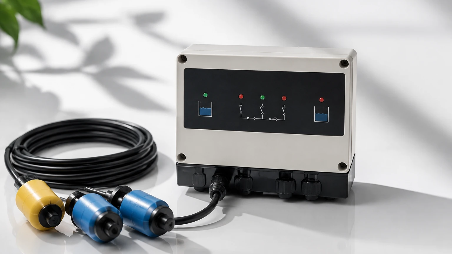
Magnetic level gauges and switches use buoyancy to track the water level. A float containing a magnet moves with the water level, triggering reed switches or a resistive chain. These are often used for simple point-level control (start/stop functions) in 24 V systems.
Technical Specifications and Selection Criteria
When evaluating a 24 V water level controller, several technical parameters must be confirmed to ensure the device meets the specific requirements of the industrial process. The standard 24 V DC supply is preferred in modern plants because it falls under the Safety Extra-Low Voltage (SELV) category, reducing the risk of electric shock.
Input Signal Compatibility
Most industrial 24 V controllers are designed to accept:
* Analog Inputs: 4-20 mA or 0-10 V signals, allowing for continuous level monitoring and variable speed drive (VSD) control.
* Digital/Switch Inputs: Discrete signals from float switches or conductivity probes for high/low alarm functions.
* Communication Protocols: RS485 Modbus or HART protocols for integration into wider SCADA systems.
Output Configurations
The controller must be able to act on the data received. Common outputs include:
* Relay Outputs: Potential-free contacts used to start or stop 24 V DC solenoid valves or trigger larger motor starters.
* Transistor Outputs (PNP/NPN): High-speed switching for electronic circuits.
* Analog Retransmission: Passing a scaled 4-20 mA signal to a remote display or PLC.
Practical Selection Table
| Sensor Type | Best Application | Accuracy | 24 V Power Consumption | Typical Range |
| :— | :— | :— | :— | :— |
| Radar | Chemical tanks, high precision | ±2 mm | 20-35 mA | Up to 30 m |
| Ultrasonic | Open channels, water pits | ±0.25% of range | 25-40 mA | 0.3 m – 15 m |
| Hydrostatic | Deep wells, vented tanks | ±0.5% FS | 15-25 mA | 1 m – 200 m |
| Magnetic | High-pressure boilers | ±5 mm | < 15 mA | 0.5 m – 6 m |
Installation Considerations for 24 V Controllers
Correct installation is critical to the longevity and accuracy of a 24 V water level controller. Because DC systems are sensitive to voltage drops and electromagnetic interference (EMI), specific guidelines must be followed.
Wiring and Shielding
For 24 V DC signal lines, especially 4-20 mA loops, twisted-pair shielded cabling is recommended. The shield should be grounded at a single point (usually the controller or PLC end) to prevent ground loops. In long-distance runs (over 100 meters), the resistance of the wire can cause a voltage drop; engineers should calculate the wire gauge (AWG) to ensure the sensor still receives the minimum required operating voltage (typically 12-15 V DC at the device end).
Environmental Protection
Controllers installed in the field require appropriate Ingress Protection (IP) ratings. For water treatment applications, an IP65 or IP66 rating is standard to protect against moisture and dust. If the controller is mounted inside a control cabinet, ensure adequate ventilation, as even low-voltage DC components generate heat during continuous operation.
Mounting the Sensor
* Radar/Ultrasonic: Must be mounted perpendicular to the water surface. Avoid placing the sensor near the tank wall or near infill pipes to prevent false echoes.
* Hydrostatic: Ensure the vent tube in the cable is not kinked or blocked, as this is necessary to compensate for atmospheric pressure changes.
Limitations and Common Risks
While 24 V water level controllers are robust, they are not without limitations. Understanding these risks helps in designing a more resilient system.
1. Power Supply Stability: 24 V DC systems require a regulated power supply. Fluctuations in the mains AC power can translate to noise in the DC circuit if the power supply unit (PSU) is of poor quality. This noise can lead to erratic level readings.
2. Signal Interference: High-voltage AC cables (e.g., 400 V motor leads) should never be run in the same conduit as 24 V DC signal wires. The electromagnetic field from the AC lines can induce currents in the DC lines, causing "ghost" signals.
3. Media Characteristics: For contact-based sensors, the chemical composition of the water (salinity, acidity, or presence of solids) can cause corrosion or buildup on the probes. In such cases, non-contact radar or ultrasonic solutions are preferred.
4. Temperature Limits: Most standard 24 V controllers are rated for operation between -20°C and +60°C. In extreme environments, such as outdoor installations in frigid climates or near high-heat industrial processes, specialized enclosures or heaters may be required.
Frequently Asked Questions (FAQs)
Q: Can I use a 24 V water level controller with a 230 V pump?
A: Yes, but not directly. The 24 V controller typically switches a relay or a contactor. The 24 V signal energizes the coil of the contactor, which then closes the high-voltage circuit to power the 230 V or 400 V pump.
Q: What is the maximum distance I can run a 4-20 mA signal from the sensor to the controller?
A: With proper 24 V DC power and shielded cable, a 4-20 mA signal can effectively travel up to 1,000 meters. However, voltage drop must be accounted for to ensure the sensor has enough voltage to operate at the full 20 mA output.
Q: How do I calibrate a 24 V controller for a non-linear tank (e.g., a horizontal cylindrical tank)?
A: Most modern digital controllers include a "strapping table" or linearization function. You input the volume corresponding to specific height increments, and the controller calculates the volume based on the level sensor's linear output.
Q: Is a 24 V system safe for hazardous areas?
A: 24 V DC is often used in intrinsically safe (IS) circuits. By using an IS barrier between the controller and the sensor located in the hazardous zone, the energy is limited to levels that cannot ignite an explosive atmosphere.
Summary and Engineering Confirmation
Selecting a 24 V water level controller requires a holistic view of the fluid properties, the physical environment, and the existing control infrastructure. By standardizing on 24 V DC, facilities benefit from a safer working environment and easier integration with modern automation hardware.
Before finalizing a purchase or installation, project teams should confirm the following:
* The maximum and minimum expected water levels (including surge levels).
* The chemical compatibility of the sensor materials with the liquid.
* The total current draw on the 24 V DC power supply to prevent overloading.
* The required communication interface for data logging or remote monitoring.
For those seeking high-performance instrumentation and detailed technical support for level measurement projects, you can Review product options and application support at the Welk Main Page. Utilizing professional-grade sensors ensures that your 24 V control loop remains accurate, reliable, and maintenance-free over its operational lifespan.