Float Level Sensor
Float Level Sensor
In the landscape of industrial automation and process control, the float level sensor remains one of the most reliable and widely utilized technologies for monitoring liquid levels. Despite the emergence of non-contact methods like radar and ultrasonic sensors, the fundamental physics of buoyancy provides a level of dependability that is difficult to replicate in specific high-pressure or high-temperature environments. For engineers and procurement specialists, understanding the nuances of float-based measurement is essential for ensuring long-term operational efficiency and safety.
As a professional manufacturer of industrial level measurement instruments, Welk provides a comprehensive range of solutions designed to meet the rigorous demands of water treatment, chemical processing, and oil and gas industries. This guide explores the engineering principles, selection criteria, and practical application of float level sensors to help technical teams make informed decisions.
Measurement Principles of Float Level Sensors
The operation of a float level sensor is governed by Archimedes' Principle, which states that any object, wholly or partially immersed in a fluid, is buoyed up by a force equal to the weight of the fluid displaced by the object. In practical instrumentation, this principle is applied through a buoyant component—the float—that moves vertically along a stem or pivots on a mechanical arm as the liquid level rises or falls.
Magnetic Coupling and Reed Switches
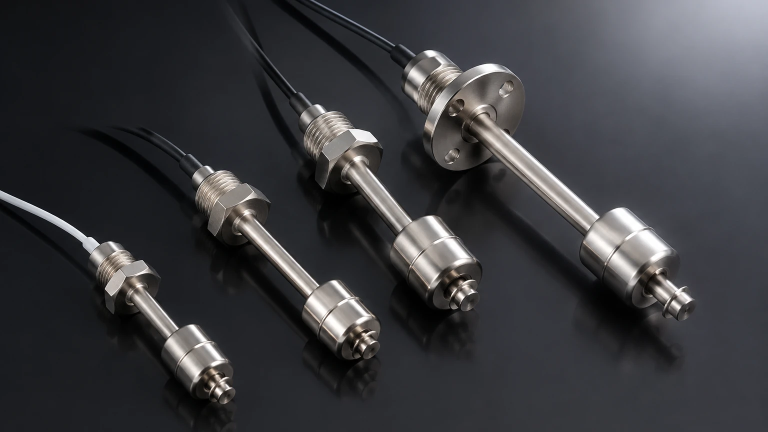
Most modern industrial float level sensors utilize magnetic coupling to translate the physical position of the float into an electrical signal. Inside the hollow float is a permanent magnet. The stationary stem contains one or more hermetically sealed reed switches.
As the liquid level changes, the float slides along the stem. When the float's internal magnet reaches the position of a reed switch, the magnetic field causes the switch contacts to close (or open, depending on the configuration). This provides a discrete point-level signal. For continuous level measurement, a series of reed switches and resistors are arranged in a ladder network. The float moves along this chain, altering the total resistance of the circuit, which is then converted into a standard 4-20mA or 0-10V analog signal proportional to the liquid height.
Magnetostrictive Technology
For high-precision applications requiring sub-millimeter accuracy, float level sensors may employ magnetostrictive technology. In this design, a low-current pulse is sent down a sensing wire made of magnetostrictive material inside the stem. When this pulse reaches the magnetic field of the float, a torsional wave is generated and travels back to the electronics head. By measuring the time-of-flight of this wave, the sensor determines the float's position with extreme precision, often within ±0.1 mm (±0.004 inches).
Key Types of Float Level Sensors
Choosing the right sensor requires an understanding of the specific mechanical configuration required for the tank or vessel.
1. Single-Point Float Switches: Used primarily for high-level alarms or low-level pump protection. These are simple, cost-effective, and highly reliable for basic on/off control.
2. Multi-Point Float Switches: A single stem containing multiple reed switches allows for several control points (e.g., Pump Start, Pump Stop, and High-Level Alarm) within a single tank penetration.
3. Continuous Float Level Transmitters: These provide a constant output of the liquid level, suitable for inventory management and precise process control.
4. Side-Mounted Horizontal Floats: Ideal for tanks where top access is restricted. The float is attached to a hinged arm that activates a switch as it pivots.
Technical Selection Criteria
To ensure the longevity of a float level sensor, several environmental and physical factors must be evaluated. Failure to account for these variables can lead to mechanical failure or inaccurate readings.
Specific Gravity (Density)
The float must be lighter than the liquid it is intended to measure. Industrial floats are typically rated for a minimum specific gravity (SG). If the liquid density is too low (e.g., certain light hydrocarbons with an SG of 0.5), a standard float designed for water (SG 1.0) will sink. Engineers must confirm the fluid's density at operating temperatures, as density decreases as temperature rises.
Material Compatibility
The wetted parts—the float, stem, and fittings—must be chemically compatible with the process media.
* Stainless Steel (316L): The standard for food and beverage, pharmaceutical, and high-pressure oil applications. It offers excellent corrosion resistance and can withstand temperatures up to 200°C (392°F) or higher in specialized designs.
* Polypropylene (PP): Suitable for acidic or alkaline solutions where metallic components would corrode.
* PVDF/PTFE: Reserved for highly aggressive chemical environments, such as concentrated sulfuric acid or chlorine solutions.
Pressure and Temperature
Standard plastic floats are often limited to atmospheric pressure or low-pressure tanks. In high-pressure vessels, such as boiler drums or pressurized chemical reactors, stainless steel or titanium floats are required to prevent the float from collapsing under external pressure. Operating pressures can range from vacuum to over 40 Bar (580 PSI) depending on the float wall thickness.
Selection Table for Float Level Sensors
| Application Requirement | Recommended Material | Max Temp (Approx.) | Max Pressure (Approx.) |
| :— | :— | :— | :— |
| Potable Water / HVAC | Polypropylene (PP) | 80°C (176°F) | 2 Bar (29 PSI) |
| Corrosive Chemicals | PVDF / PTFE | 100°C (212°F) | 5 Bar (72.5 PSI) |
| High-Temp Oil / Steam | 316L Stainless Steel | 200°C+ (392°F+) | 40 Bar (580 PSI) |
| Food & Beverage | Polished 316L SS | 120°C (248°F) | 10 Bar (145 PSI) |
| Low Density Fluids | Titanium / Thin-wall SS | 150°C (302°F) | 15 Bar (217 PSI) |
Installation Considerations
Proper installation is critical to the performance of a float level sensor. Even the most robust sensor will fail if mechanical interference occurs.
Vertical Alignment
For stem-type sensors, the unit must be installed vertically. A tilt of more than 15 degrees can increase friction between the float and the stem, leading to "sticking." If a tank has a sloped roof, a mounting flange or threaded boss must be leveled to ensure verticality.
Avoiding Turbulence
In tanks with high-velocity inlets or agitators, the physical movement of the liquid can cause the float to bounce or oscillate, leading to "chatter" in the electrical signal. In these environments, a stilling well (a bypass pipe or internal perforated tube) should be used. The stilling well creates a calm area for the float while allowing the liquid level to equalize with the rest of the tank.
Magnetic Interference
Since many float sensors rely on internal magnets, they should be kept away from strong external magnetic fields or large ferrous structures that could distort the magnetic flux and cause false switching. If the tank itself is made of carbon steel, ensure the float has sufficient clearance from the tank walls (typically at least 50mm or 2 inches).
Limitations and Risks
While highly reliable, float level sensors are not universal solutions. Engineers should be aware of the following risks:
1. Coating and Scaling: In liquids that are prone to crystallization or heavy coating (e.g., wastewater with high grease content or lime slurry), material can build up on the stem. This increases friction and eventually causes the float to seize in a fixed position.
2. Particulate Matter: Large solids or fibrous materials can become lodged between the float and the stem, preventing movement.
3. Mechanical Wear: Because it is a contact-based technology with moving parts, the float and stem will eventually experience wear, especially in applications with frequent level cycling.
4. Specific Gravity Shifts: If a process involves mixing different fluids with varying densities, the buoyancy of the float will change, leading to measurement errors.
For applications involving heavy slurries or extremely viscous liquids, non-contact technologies like radar may be more appropriate. You can Review product options and application support on our main site to compare these technologies side-by-side.
Frequently Asked Questions (FAQ)
Q: Can a float level sensor be used in explosive environments?
A: Yes, provided they are designed as intrinsically safe (IS) or explosion-proof (Ex d) devices. Since the sensing element is often a simple reed switch, they are easily integrated into IS circuits using a Zener barrier.
Q: How do I maintain a float level sensor?
A: Maintenance primarily involves periodic inspection for build-up. In clean water applications, they may function for years without intervention. In chemical applications, the stem should be wiped down during scheduled shutdowns to ensure the float moves freely.
Q: What is the difference between a float switch and a float transmitter?
A: A float switch provides a digital (on/off) signal at specific points. A float transmitter provides a continuous analog signal (e.g., 4-20mA) representing the exact level across the entire sensing range.
Q: Can I use a stainless steel float in a plastic tank?
A: Yes, stainless steel floats are often used in plastic tanks for chemical compatibility with the liquid or to handle higher temperatures than plastic floats can tolerate.
Conclusion and Next Steps
The float level sensor remains a cornerstone of industrial level measurement due to its simplicity and high reliability in clean liquid applications. When selecting a sensor, the priority must be placed on material compatibility, fluid density, and the physical dynamics of the tank environment.
Before finalizing a specification, project teams should confirm:
* The minimum and maximum operating temperature and pressure.
* The specific gravity of the liquid at those temperatures.
* The presence of any solids or potential for scaling.
* The required output signal (switch vs. continuous).
For detailed technical specifications and to explore our full range of level measurement instrumentation, visit our Main Page. Our engineering team is available to provide customized OEM/ODM services to ensure your level measurement solution is perfectly matched to your industrial automation needs.