Sick Ultrasonic Flow Meter
Sick Ultrasonic Flow Meter
Ultrasonic flow measurement has become a cornerstone of modern industrial process control and custody transfer. Among the leading technologies in this field, the Sick ultrasonic flow meter series—specifically the FLOWSIC family—is recognized for its precision in gas and liquid applications. These instruments leverage acoustic waves to determine the velocity of a moving medium without the need for moving parts, which significantly reduces maintenance requirements and pressure loss across the system.
For engineers and plant managers, selecting the correct flow meter involves understanding the specific physics of ultrasound, the environmental constraints of the installation site, and the regulatory requirements of the industry. This guide provides a technical overview of ultrasonic flow measurement principles, selection criteria for Sick-specific technologies, and practical installation guidance.
Measurement Principles of Ultrasonic Flow Meters
Before selecting a specific model, it is essential to understand the two primary methods used in ultrasonic flow measurement: transit-time difference and the Doppler effect. Most industrial-grade meters, including the Sick FLOWSIC series, primarily utilize the transit-time principle for clean liquids and gases.
Transit-Time Difference Principle
In this method, two ultrasonic transducers are mounted opposite each other at a specific angle. They act as both transmitters and receivers. The meter sends acoustic pulses simultaneously or in rapid succession in both directions: one with the flow (downstream) and one against the flow (upstream).
* Downstream Pulse: Travels faster because the moving medium carries the sound wave.
* Upstream Pulse: Travels slower as it must overcome the resistance of the flow.
The time difference (Δt) between these two pulses is directly proportional to the flow velocity. By integrating this velocity with the cross-sectional area of the pipe, the meter calculates the volumetric flow rate. Modern high-end meters use multiple "paths" (pairs of transducers) to account for non-uniform flow profiles, ensuring high accuracy even in turbulent conditions.
Doppler Effect Principle
The Doppler method relies on sound waves reflecting off particles or bubbles within the fluid. As the sound hits a moving object, the frequency of the reflected signal shifts. This shift is proportional to the velocity of the particle. While useful for slurries or heavily aerated liquids, this method is less common in high-precision gas measurement compared to transit-time technology.
Technical Evaluation Criteria for Sick Ultrasonic Flow Meters
When evaluating a Sick ultrasonic flow meter for a specific application, several technical parameters must be confirmed to ensure long-term reliability and accuracy.
1. Medium Characteristics
Sick specializes heavily in gas flow measurement. The FLOWSIC600, for instance, is a benchmark for natural gas custody transfer. You must define:
* Gas Composition: Is it dry natural gas, wet gas, or flare gas with high CO2 content?
* Liquid Properties: For liquid meters, viscosity and the presence of suspended solids are critical factors.
2. Operating Pressure and Temperature
Ultrasonic sensors are sensitive to the density of the medium, which is a function of pressure and temperature. High-pressure applications (e.g., 10 MPa to 45 MPa) require specialized transducer housings to prevent mechanical failure and signal attenuation. Conversely, cryogenic or high-heat applications require specific thermal decoupling.
3. Accuracy and Uncertainty Requirements
For custody transfer (where money changes hands based on the reading), an uncertainty of less than 0.1% to 0.5% is often required. For process monitoring or leak detection, a higher uncertainty (1.0% to 2.0%) may be acceptable and more cost-effective.
Comparative Selection Table
The following table outlines common categories of ultrasonic flow meters often encountered in industrial specifications, including those aligned with Sick’s technological strengths.
| Feature | Custody Transfer (e.g., FLOWSIC600) | Process Control (e.g., FLOWSIC500) | Flare/Waste Gas (e.g., FLOWSIC100) |
| :— | :— | :— | :— |
| Typical Accuracy | ±0.1% to ±0.5% | ±0.5% to ±1.0% | ±2.0% to ±5.0% |
| Path Configuration | 4 to 8 paths | 1 to 2 paths | 1 path (cross-duct) |
| Medium | Clean Natural Gas | Mixed Gases / Air | Contaminated / Wet Gas |
| Pipe Sizes | DN100 – DN1200 | DN50 – DN300 | DN100 – DN2000+ |
| Redundancy | High (Self-diagnostics) | Moderate | Low |
| Maintenance | Periodic calibration | Minimal | Occasional cleaning |
Installation Best Practices and Engineering Requirements
The performance of a Sick ultrasonic flow meter is heavily dependent on the hydraulic or pneumatic conditions at the point of installation. Even the most advanced 8-path meter cannot fully compensate for a poorly designed piping layout.
Straight Pipe Run Requirements
To ensure a stable, laminar flow profile, straight sections of pipe are required both upstream and downstream of the meter.
* Upstream: Typically 10 to 20 times the nominal diameter (DN).
* Downstream: Typically 3 to 5 times the nominal diameter (DN).
If the installation space is limited, flow conditioners (perforated plates) may be necessary to eliminate swirl and turbulence caused by elbows, valves, or reducers.
Orientation and Mounting
* Horizontal Installation: This is the preferred orientation for most gas flow meters. Transducers should be positioned in the 3 o'clock and 9 o'clock positions to prevent moisture or debris from settling on the sensor faces.
* Vertical Installation: Possible for clean liquids or gases, provided the flow is upward to ensure the pipe remains completely full.
Signal Interference
Ultrasonic meters can be affected by ultrasonic noise generated by control valves or pressure regulators located too close to the meter. This noise can "drown out" the meter's signal. Engineering designs should include sufficient distance or noise-attenuating bends between the flow meter and such valves.

Limitations and Operational Risks
While highly versatile, ultrasonic flow meters have specific limitations that engineers must mitigate:
1. Signal Attenuation: In gas applications, high concentrations of CO2 or very high velocities can absorb or scatter the ultrasonic signal, leading to "signal loss" errors.
2. Contamination: While non-intrusive, the buildup of wax, scale, or moisture on the internal pipe wall or transducer faces can change the internal diameter or weaken the signal pulse.
3. Minimum Flow Velocity: Ultrasonic meters have a "low-flow cutoff." If the velocity is too low (typically below 0.1 m/s), the time difference becomes too small to measure accurately.
4. Power Requirements: High-precision meters with advanced diagnostics often require stable 24V DC power and are not always suitable for battery-powered remote locations without solar support.
Integration of Flow and Level Measurement
In many industrial environments, such as chemical processing or water treatment, flow measurement is only one part of the mass balance equation. To accurately manage inventory and process safety, flow data from a Sick ultrasonic flow meter is often paired with precise level measurement data from storage tanks and process vessels.
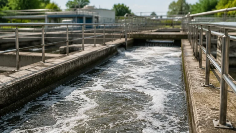
For instance, in a wastewater treatment plant, ultrasonic flow meters measure the influent rate while hydrostatic or ultrasonic level transmitters monitor the basin levels. For comprehensive industrial measurement solutions, including radar level meters and ultrasonic level sensors that complement these flow systems, engineers often visit the Main Page to evaluate advanced level measurement technologies from manufacturers like Welk. Integrating these two data points allows for real-time leak detection and automated pump control.
Frequently Asked Questions (FAQs)
Can a Sick ultrasonic flow meter measure steam?
Most standard FLOWSIC models are designed for gas or liquids. Steam measurement requires specialized high-temperature transducers and compensation for the unique acoustic properties of water vapor. Always check the specific model's temperature rating.
How often does an ultrasonic flow meter need calibration?
For custody transfer, local regulations (such as those from the AGA or OIML) usually dictate calibration intervals, often every 2 to 5 years. For general process use, the internal self-diagnostics of the Sick meter can often alert the user if a calibration shift is detected, potentially extending the interval.
What is the difference between "In-line" and "Clamp-on" ultrasonic meters?
* In-line: The meter is a spool piece bolted into the pipeline. It is more accurate and used for permanent installations.
* Clamp-on: Transducers are strapped to the outside of the pipe. These are ideal for retrofitting or temporary surveys but generally offer lower accuracy (±1% to ±3%) due to uncertainties in pipe wall thickness and material.
Does pipe material affect the measurement?
For in-line meters, the pipe material is part of the calibrated spool. For clamp-on applications, the material (e.g., carbon steel, PVC, stainless steel) significantly impacts how sound travels through the wall, requiring precise input of the pipe's sonic velocity into the meter's software.
How does the meter handle changing gas compositions?
Advanced ultrasonic meters measure the "speed of sound" in the medium. Since the speed of sound changes with gas composition, the meter can use this data to perform internal diagnostics or even estimate the gas quality (e.g., BTU content in natural gas) when integrated with a flow computer.
By following these engineering guidelines and selecting the appropriate path configuration for the application, the Sick ultrasonic flow meter provides a reliable, long-term solution for complex fluid dynamics. For those managing the broader scope of tank farm automation, ensuring that level measurement instruments are equally robust is the next logical step in system optimization.