Flow Meter Usa
Flow Meter Usa
In the industrial landscape of the United States, accurate flow measurement is a cornerstone of process control, environmental compliance, and resource management. Whether in the vast municipal water treatment plants of the Midwest or the complex chemical refineries along the Gulf Coast, the demand for reliable instrumentation is constant. While flow and level measurement are often viewed as distinct disciplines, they are fundamentally linked in many B2B applications. This guide explores the principles of flow measurement, the integration of level-sensing technology into flow calculations, and the criteria for selecting instrumentation within the USA industrial sector.
Understanding Flow Measurement Principles in Industrial Applications
Before selecting a specific instrument, it is essential to understand the physical principles that govern how fluids are measured. In the context of a flow meter USA application, engineers generally categorize measurement methods into three primary types: differential pressure, velocity measurement, and area-velocity methods.
Differential Pressure (DP)
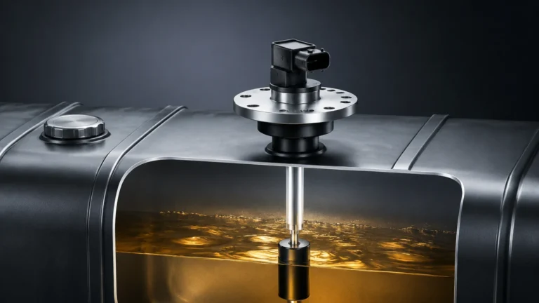
Differential pressure is one of the oldest and most established methods. It relies on Bernoulli’s principle, which states that as the speed of a moving fluid increases, the pressure within the fluid decreases. By placing a restriction in a pipe (such as an orifice plate or Venturi tube), a pressure drop is created. The square root of this pressure drop is proportional to the flow rate. Hydrostatic level transmitters are frequently used in these setups to measure the pressure across the restriction with high precision.
Velocity Measurement
Velocity-based meters measure the speed at which a fluid moves through a known cross-sectional area. Common technologies include:
- Ultrasonic (Transit-time): These meters send sound pulses across the flow path. The difference in time between pulses traveling with the flow and against it determines the velocity.
- Radar (Non-contact): Using the Doppler effect, radar sensors measure the surface velocity of a liquid. This is increasingly popular in the USA for wastewater and irrigation applications where contact with the medium is discouraged.
Area-Velocity Method
This method is primarily used in open channels or partially filled pipes. It requires two measurements: the level (depth) of the liquid and the average velocity. By knowing the geometry of the channel, the instrument calculates the cross-sectional area and multiplies it by the velocity to determine the total volumetric flow.
Open Channel Flow Measurement via Level Sensing
One of the most common ways level measurement instruments function as flow meters is in open channel applications. In the USA, regulatory bodies like the EPA often require precise monitoring of effluent discharge. This is typically achieved using primary devices such as flumes or weirs.
The Role of Ultrasonic and Radar Level Meters
In an open channel system, a primary device creates a known relationship between the liquid level and the flow rate. An ultrasonic or radar level sensor is mounted above the channel to measure the "head" (the height of the liquid).
1. Ultrasonic Sensors: These are cost-effective and reliable for clean water applications. They emit high-frequency sound waves that bounce off the liquid surface. The time-of-flight is converted into a distance measurement, which is then translated into flow via a pre-programmed flow curve (e.g., a Parshall flume curve).
2. Radar Level Meters: For applications involving high temperatures, steam, or varying vapor densities—common in chemical processing—80GHz high-frequency radar is preferred. Unlike ultrasonic waves, radar signals are not affected by air temperature or turbulence, providing a more stable reading in harsh environments.
For those seeking comprehensive instrumentation options, you can Review product options and application support to see how these level technologies integrate into broader flow management systems.
Selecting the Right Flow Meter for USA Industrial Standards
Choosing the correct instrument requires an evaluation of the fluid properties, the installation environment, and the required accuracy. The following table provides a comparison of technologies commonly utilized in the USA market for flow-related applications.
Technology Comparison Table
| Technology | Primary Application | Accuracy | Pros | Cons |
| :— | :— | :— | :— | :— |
| Ultrasonic Level (for Flow) | Open channels, weirs, flumes | ±0.25% to 0.5% | Non-contact, low maintenance | Sensitive to heavy foam and wind |
| Radar Level (for Flow) | Harsh chemical channels, high-temp | ±1 mm to 2 mm | Unaffected by steam/vapor, high precision | Higher initial cost |
| Hydrostatic Pressure | DP flow in pipes, tank discharge | ±0.1% to 0.2% | Robust, handles high pressure | Requires contact with fluid |
| Magnetic Flow Meter | Conductive liquids, slurries | ±0.5% | No moving parts, no pressure drop | Only for conductive fluids |
| Thermal Mass Flow | Gas flow measurement | ±1% | Direct mass flow measurement | Sensitive to moisture and debris |
When evaluating a flow meter USA provider, it is vital to confirm that the equipment meets local standards, such as those set by the American Society of Mechanical Engineers (ASME) or the American National Standards Institute (ANSI).

Installation Considerations and Best Practices
Even the most advanced flow meter will fail to provide accurate data if installed incorrectly. In the USA industrial sector, adherence to straight-pipe requirements and environmental shielding is paramount.
Straight-Pipe Requirements
For velocity-based and DP meters, the flow profile must be stable and laminar. This typically requires a straight run of pipe upstream (often 10 to 20 diameters) and downstream (5 diameters) of the meter. If these distances cannot be met, flow conditioners or vanes may be necessary to eliminate turbulence.
Mounting and Orientation
- Non-contact Sensors: For open channel flow, the sensor must be mounted perpendicular to the liquid surface. In the USA, many outdoor installations use sunshades to prevent the sensor housing from overheating, which can affect internal temperature compensation in ultrasonic models.
- Hydrostatic Transmitters: These should be installed at the lowest point of the measurement range. In colder climates (e.g., the Northern USA), heat tracing or insulation may be required to prevent the process fluid from freezing in the impulse lines.
Calibration and Verification
Regular calibration is a standard requirement for ISO-certified facilities. Many modern instruments now feature "in-situ" verification, allowing technicians to check the health of the sensor electronics without removing the meter from the process line. This reduces downtime and maintenance costs significantly.
Limitations and Challenges in Flow Measurement
No single measurement technology is universal. Understanding the limitations of your chosen flow meter is critical for long-term operational success.
1. Media Characteristics: High viscosity, aeration (bubbles), or high solids content can interfere with ultrasonic signals. In such cases, radar or electromagnetic meters are often more suitable.
2. Environmental Interference: In outdoor open channel applications, heavy wind or significant temperature fluctuations can distort ultrasonic sound waves. Radar is immune to these factors but may struggle with very low dielectric constant fluids (though this is rarely an issue in water-based flow).
3. Signal Obstruction: For non-contact meters, any physical obstruction between the sensor and the fluid—such as internal bracing in a tank or a buildup of debris on a weir—will result in false readings.
Frequently Asked Questions (FAQ)
Q: Can I use a level sensor to measure flow in a closed pipe?
A: Only if the pipe is partially filled and the geometry is known (Area-Velocity method). For full pipes, a dedicated inline flow meter or a clamp-on ultrasonic flow meter is required.
Q: What is the advantage of 80GHz radar for flow measurement?
A: The 80GHz frequency allows for a narrower beam angle (often as small as 3 degrees). This means the sensor can avoid hitting the sides of narrow channels or flumes, providing a much cleaner signal and more accurate flow data.
Q: How do I handle flow measurement in a corrosive environment?
A: Non-contact methods (Radar/Ultrasonic) are ideal because the sensor does not touch the corrosive media. Ensure the sensor housing is rated for the environment (e.g., NEMA 4X or IP67/68).
Q: What units are standard for flow meters in the USA?
A: While many industries are moving toward metric (m³/h or liters per second), imperial units remain common. Most modern digital meters allow the user to toggle between Gallons Per Minute (GPM), Million Gallons per Day (MGD), and metric equivalents.
Q: Does Welk offer customized solutions for flow measurement?
A: Yes, as a professional manufacturer, Welk provides OEM/ODM services, allowing for customized sensor configurations and integration options to meet specific industrial automation needs globally, including the USA market.
For more detailed technical specifications and to explore the full range of instrumentation available for your project, visit the Main Page of our product catalog. By understanding the principles and selecting the appropriate technology, engineers can ensure precise, cost-effective, and reliable flow measurement across any application.