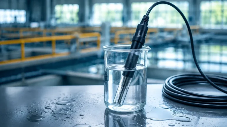
Flow Metering
Flow Metering
In the landscape of industrial process control, flow metering stands as a critical pillar alongside level, pressure, and temperature measurement. It is the process of quantifying the movement of liquids, gases, or steam through a closed pipe or an open channel. For engineers and facility managers, selecting the correct flow metering technology is not merely a matter of measuring volume; it is about ensuring process efficiency, maintaining safety standards, and achieving cost-effective operations.
Welk, a professional manufacturer of industrial measurement instruments, provides a wide array of solutions that bridge the gap between level detection and flow analysis. Understanding the physics behind these measurements is the first step toward optimizing any industrial system. This guide explores the principles of flow metering, its relationship with level measurement, and the practical considerations required for successful implementation.
Fundamental Principles of Flow Metering
Flow metering technologies are categorized based on the physical principles they employ to derive the flow rate. Before selecting a device, it is essential to understand how these methods interact with the fluid.
Differential Pressure (DP) Flow Meters
Differential pressure is one of the most established methods for flow metering. It operates on Bernoulli’s principle, which states that as the speed of a moving fluid increases, the pressure within the fluid decreases. By placing a primary element—such as an orifice plate, Venturi tube, or flow nozzle—inside the pipe, a constriction is created. This constriction causes a pressure drop between the upstream and downstream sides. The square root of this pressure difference is proportional to the flow rate. While reliable, DP meters introduce a permanent pressure loss into the system, which must be accounted for in pumping costs.
Electromagnetic Flow Meters (Magmeters)
Magmeters operate based on Faraday’s Law of Electromagnetic Induction. This principle states that a conductor moving through a magnetic field produces an electrical signal. In this application, the conductive liquid (such as water or chemicals) acts as the conductor. As the liquid flows through a magnetic field generated by the meter, it creates a voltage proportional to its velocity. Because they have no moving parts and offer no obstruction to the flow, magmeters are ideal for slurries and corrosive liquids, provided the fluid has a minimum conductivity (typically >5 μS/cm).
Ultrasonic Flow Metering
Ultrasonic meters use sound waves to determine fluid velocity. There are two primary types:
1. Transit-Time: These meters send pulses of high-frequency sound across the pipe. The time difference between the pulse traveling with the flow and the pulse traveling against the flow is used to calculate velocity. These are best suited for clean liquids.
2. Doppler: These meters reflect sound waves off bubbles or particles in the fluid. The frequency shift (Doppler effect) indicates the velocity. These are preferred for aerated liquids or fluids with suspended solids.
Vortex Flow Meters
Vortex shedding is a principle observed when a fluid passes a "shedder bar" or bluff body. This creates oscillating vortices (the Karman vortex street) downstream. The frequency at which these vortices are shed is directly proportional to the fluid velocity. Vortex meters are highly versatile, capable of measuring liquids, gases, and steam, and are known for their long-term stability since they have no moving parts to wear out.
Flow Measurement in Open Channels via Level Sensing
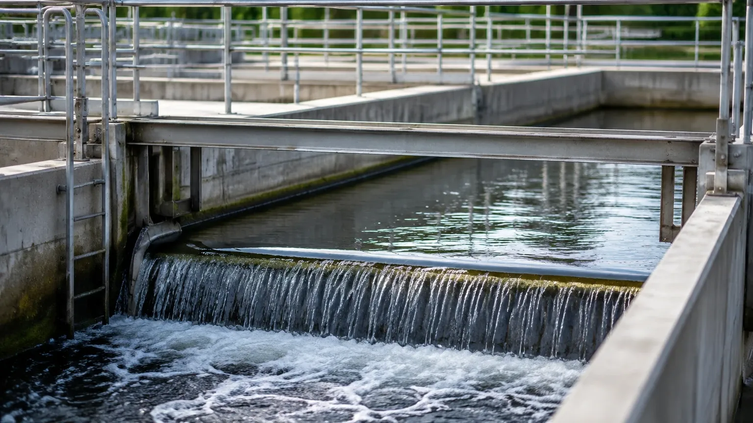
In many water treatment and environmental applications, fluids are not contained within pipes but flow through open channels, flumes, or weirs. In these scenarios, flow metering is achieved indirectly through level measurement. This is a core area of expertise for Welk, where radar and ultrasonic level sensors are utilized to calculate discharge rates.
By installing a primary device like a Parshall flume or a V-notch weir, a known relationship is established between the liquid level (head) and the flow rate. An ultrasonic level sensor is mounted above the channel to measure the distance to the water surface. The internal electronics of the transmitter then convert this level reading into a flow volume (e.g., m³/h or GPM) using pre-programmed hydraulic formulas. This non-contact method is highly effective for wastewater and irrigation because it avoids fouling and maintenance issues associated with submerged sensors.
Key Selection Criteria for Industrial Flow Meters
Choosing the right flow metering technology requires a detailed analysis of the application environment. No single technology fits every scenario. Engineers should evaluate the following criteria:
Fluid Properties
* Phase: Is the fluid a liquid, gas, or steam? Multiphase flows (e.g., liquid with gas bubbles) require specialized meters like Coriolis or specific ultrasonic types.
* Conductivity: Only conductive fluids can be measured with electromagnetic meters.
* Viscosity: High-viscosity fluids can affect the accuracy of turbine or DP meters but are often handled well by positive displacement or Coriolis meters.
* Corrosivity: The materials of construction (liners and electrodes) must be compatible with the chemical makeup of the fluid.
Process Conditions
* Flow Range (Turndown Ratio): This is the ratio of the maximum flow to the minimum flow that the meter can accurately measure. If your process has high variability, you need a meter with a wide turndown ratio, such as an ultrasonic or electromagnetic meter.
* Accuracy and Repeatability: Critical custody transfer applications require high accuracy (0.1% to 0.5%), whereas general process monitoring might only require 1% to 2% accuracy.
* Pressure and Temperature: Ensure the meter body and sensors can withstand the maximum operating pressure (in bar or PSI) and temperature ranges of the system.
Practical Selection Table
| Technology | Suitable Fluids | Accuracy (Typical) | Pressure Drop | Moving Parts |
| :— | :— | :— | :— | :— |
| Electromagnetic | Conductive Liquids | ±0.5% | None | No |
| Ultrasonic | Clean/Dirty Liquids | ±1.0% | None | No |
| Vortex | Liquid, Gas, Steam | ±1.0% | Medium | No |
| Differential Pressure | Liquid, Gas, Steam | ±1.0% to 2.0% | High | No |
| Coriolis | Liquids, Dense Gas | ±0.1% | Medium | No |
| Turbine | Clean Liquids/Gases | ±0.25% | High | Yes |
Installation Best Practices and Geometric Requirements
Even the most advanced flow meter will fail to provide accurate data if installed incorrectly. The most common cause of measurement error is "velocity profile distortion," which occurs when valves, elbows, or pumps are placed too close to the meter.
Straight Pipe Runs
Most flow metering technologies require a specific length of straight pipe both upstream and downstream of the sensor to allow the flow profile to stabilize. A common rule of thumb is the "10D and 5D" rule: 10 pipe diameters of straight run upstream and 5 pipe diameters downstream. For example, if you are using a 100 mm (4-inch) pipe, you should have 1,000 mm of straight pipe before the meter and 500 mm after it. Some technologies, like certain ultrasonic or electromagnetic meters, are more forgiving, but these requirements should always be verified in the technical manual.
Orientation and Filling
For liquid applications, the pipe must be completely full for accurate measurement. In horizontal installations, sensors should be placed such that air bubbles do not collect at the top and sediment does not settle at the bottom. For electromagnetic meters, installing the electrodes in a horizontal plane (3 o'clock and 9 o'clock positions) is standard practice. Vertical installations are often preferred for liquids, provided the flow is moving upward to ensure the pipe remains full.
Grounding and Interference
Electromagnetic flow meters are particularly sensitive to electrical noise. Proper grounding to the fluid and the piping system is mandatory to prevent stray currents from interfering with the low-voltage signal generated by the meter. Similarly, ultrasonic meters must be shielded from high-frequency vibration or acoustic noise from nearby control valves.
Limitations and Operational Risks
While modern flow metering is highly accurate, there are inherent risks and limitations that must be managed to prevent equipment failure or data inaccuracies.
1. Cavitation and Flashing: If the pressure drops below the vapor pressure of a liquid, vapor bubbles form (cavitation). When these bubbles collapse, they can cause severe physical damage to the meter internals and introduce significant measurement errors. This is a common risk with DP and vortex meters.
2. Scale and Coating: In chemical or wastewater applications, material can build up on the inner walls of the meter or on the electrodes. This changes the internal diameter of the pipe or insulates the sensors, leading to drift in accuracy. Regular maintenance and the use of non-stick liners (like PTFE) can mitigate this.
3. Gas Entrainment: Small amounts of gas in a liquid line can cause ultrasonic signals to scatter or cause Coriolis meters to stall. Air eliminators should be used if gas entrainment is a known issue.
4. Wear and Tear: Meters with moving parts, such as turbine meters, are subject to mechanical wear. Over time, the bearings may degrade, leading to under-registration of flow. These require periodic calibration and part replacement.
For a comprehensive look at the various instrumentation options available for these challenges, users can visit the Welk Main Page to review technical specifications and application support.
Frequently Asked Questions (FAQ)
Q: Can I use a flow meter to measure the level of a tank?
A: Not directly. However, by integrating the flow rate over time (totalization), you can estimate the volume change in a tank. For direct level measurement, it is better to use dedicated radar or ultrasonic level sensors.
Q: What is the difference between mass flow and volumetric flow?
A: Volumetric flow measures the space the fluid occupies (e.g., m³/h). Mass flow measures the actual weight of the fluid (e.g., kg/h). Mass flow is generally more accurate for gases and steam because their volume changes significantly with pressure and temperature.
Q: How often should a flow meter be calibrated?
A: Calibration frequency depends on the criticality of the process and the type of meter. Most industrial applications require annual calibration, while custody transfer systems may require more frequent verification. Meters with no moving parts generally hold their calibration longer.
Q: Can ultrasonic flow meters work on plastic pipes?
A: Yes, transit-time ultrasonic meters can work on most pipe materials, including PVC, PE, and stainless steel, as long as the pipe is sound-conductive and the sensor is properly coupled to the surface.
Conclusion
Flow metering is a complex but essential component of modern industrial automation. By understanding the underlying physics—whether it be differential pressure, electromagnetism, or ultrasonic transit times—engineers can make informed decisions that improve process reliability. When combined with accurate level measurement, flow data provides a complete picture of fluid dynamics within a facility.
Before proceeding with a project, it is vital to confirm fluid compatibility, pipe geometry, and the required accuracy levels. For those seeking reliable hardware and expert guidance, exploring the options on the manufacturer's Main Page provides the necessary technical foundation to ensure a successful installation. Whether you are managing water treatment, chemical processing, or industrial automation, the right flow metering strategy is the key to operational excellence.