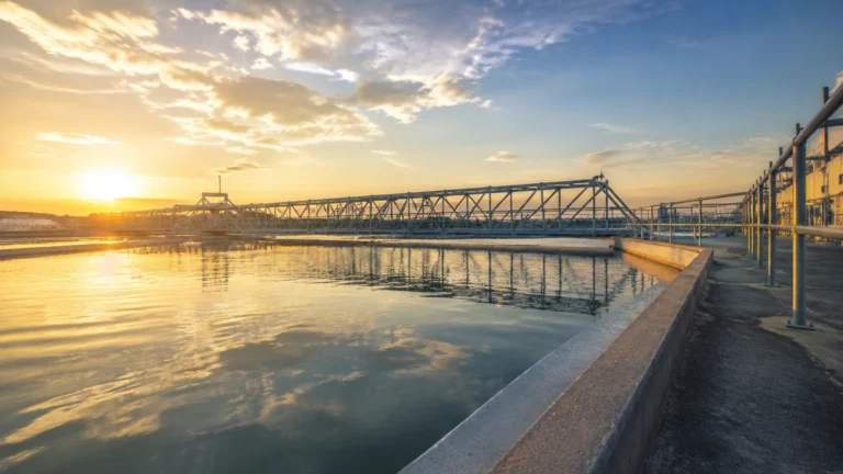
Flow Station
Flow Station
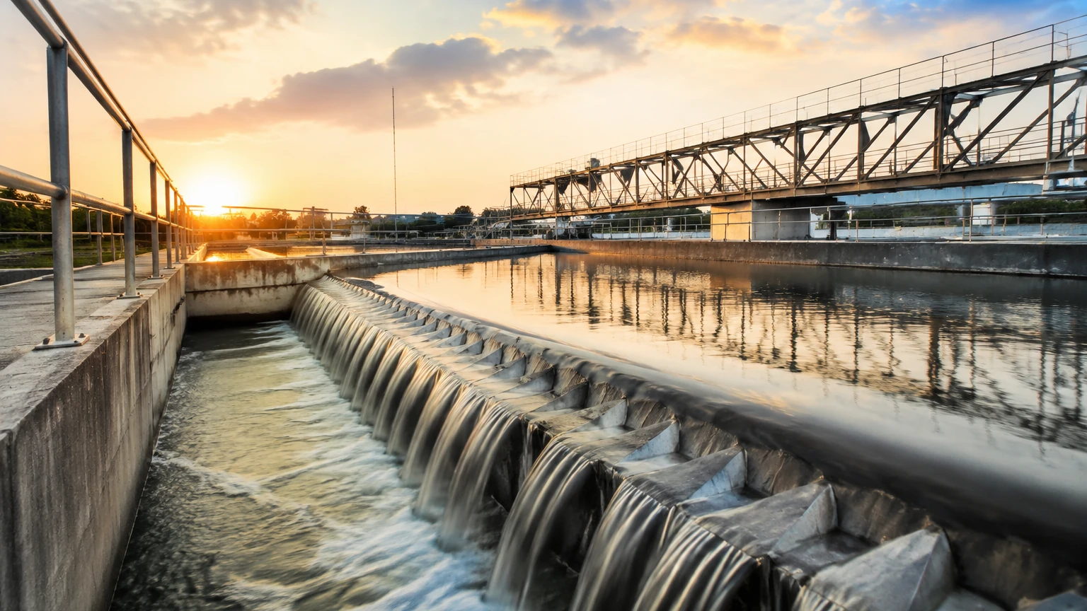
In the landscape of industrial fluid management, a flow station serves as a critical centralized hub designed to collect, process, and distribute fluids—typically oil, gas, or water—from multiple sources. Whether situated in an oil field gathering system or a municipal water distribution network, the efficiency of a flow station depends heavily on the precision of its instrumentation. Accurate monitoring of tank levels, separator interfaces, and pump sumps ensures operational safety, environmental compliance, and fiscal accountability.
For engineers and facility managers, understanding the integration of level measurement technologies within a flow station is paramount. This guide explores the fundamental principles of level sensing, selection criteria for various media, and practical installation strategies to optimize performance at the Main Page of industrial automation.
Measurement Principles in Flow Station Operations
Level measurement in a flow station is rarely a one-size-fits-all application. The choice of technology depends on the physical properties of the fluid, the process conditions (temperature and pressure), and the specific function of the vessel. Below are the primary measurement principles utilized in modern facilities.
Radar Level Measurement (FMCW and Pulse)
Radar transmitters are the gold standard for many flow station applications due to their non-contact nature. They operate by emitting high-frequency electromagnetic waves (typically in the 26 GHz or 80 GHz range).
* Principle: The device measures the time it takes for the signal to travel to the liquid surface and reflect back. Frequency Modulated Continuous Wave (FMCW) radar is particularly effective in flow stations because it calculates distance based on frequency shifts, providing superior accuracy even in the presence of vapor or light foam.
* Application: Ideal for crude oil storage tanks, chemical buffer tanks, and high-pressure separators where the media may be corrosive or volatile.
Ultrasonic Level Sensing
Ultrasonic sensors utilize sound waves rather than electromagnetic waves.
* Principle: The sensor emits an ultrasonic pulse that bounces off the surface of the media. The time-of-flight is used to calculate the distance.
* Application: These are frequently used in water-based flow stations, open-channel flow monitoring, and sumps. However, they are sensitive to air temperature fluctuations and heavy foam, which can absorb the sound signal.
Hydrostatic Pressure Measurement
Hydrostatic transmitters measure the pressure exerted by a liquid column at a fixed point.
* Principle: Based on the formula $P = \rho gh$ (where $P$ is pressure, $\rho$ is density, $g$ is gravity, and $h$ is height), the sensor converts the weight of the fluid into a level reading.
* Application: Common in vented tanks and deep wells within a flow station. They are valued for their simplicity and ease of maintenance, provided the fluid density remains relatively constant.
Magnetic Level Gauges (MLG)
For high-visibility local indication combined with remote transmission, magnetic level gauges are a staple in separator units.
* Principle: A float containing a permanent magnet moves with the liquid level inside a bypass chamber. This float flips magnetic flaps on an external scale and can be paired with a reed chain transmitter for 4-20mA output.
* Application: Excellent for high-pressure/high-temperature oil-water separators where visual confirmation is required for safety protocols.
Key Components of a Flow Station and Level Integration
A typical flow station consists of several stages where level measurement is vital for process control.
1. Inlet Manifolds and Slug Catchers: As fluids enter the station, slug catchers manage large volumes of liquid or gas. Level switches are used here to prevent liquid carryover into gas compressors.
2. Separation Vessels: These vessels split the flow into oil, gas, and water. Interface level measurement is critical here to distinguish between the oil and water layers, often requiring guided wave radar or high-precision displacement transmitters.
3. Storage Tanks: Large-scale tanks store the processed fluids before transport. High-accuracy radar (accuracy within ±2 mm or 0.08 in) is used for inventory management and custody transfer.
4. Sump and Flare Systems: Waste fluids are collected in sumps. Ultrasonic or hydrostatic sensors monitor these levels to trigger automated pump-out sequences, preventing environmental spills.
Selection Criteria for Flow Station Instrumentation
When selecting level instruments for a flow station, engineers must evaluate the following factors to ensure long-term reliability.
| Criteria | Radar (Non-contact) | Ultrasonic | Hydrostatic | Magnetic Gauge |
| :— | :— | :— | :— | :— |
| Media Type | Hydrocarbons, Chemicals | Water, Wastewater | Clean Liquids | Oil, Water, Steam |
| Accuracy | Very High (±2mm) | Moderate (±0.25%) | Moderate (±0.1%) | Good (Visual) |
| Max Temp | Up to 450°C (842°F) | Up to 80°C (176°F) | Up to 100°C (212°F) | Up to 400°C (752°F) |
| Max Pressure | Up to 160 bar (2320 psi) | Atmospheric | Varies by sensor | Up to 320 bar (4640 psi) |
| Foam Handling | Good (FMCW) | Poor | Excellent | Excellent |
| Maintenance | Low (No moving parts) | Low | Moderate | Moderate |
Installation Considerations and Best Practices
Proper installation is as important as the technology itself. In a flow station environment, several physical factors can interfere with measurement accuracy.
Nozzle Geometry
For radar and ultrasonic sensors, the mounting nozzle should be as short and wide as possible. If the nozzle is too narrow or long, it can create "ringing" or false echoes. For radar, the sensor should ideally be positioned at 1/6th to 1/4th of the tank diameter from the wall to avoid interference from wall reflections while staying clear of the central vortex created by agitators.
Avoiding Internal Obstructions
Flow station tanks often contain heating coils, ladders, and inlet pipes. Instruments must be installed with a clear "line of sight" to the liquid surface. If obstructions are unavoidable, modern radar units offer "false echo suppression" software to map out and ignore these static reflections.
Stillwells and Bypass Chambers
In applications with heavy turbulence or foam, such as the primary separation stage of a flow station, installing the level sensor inside a stillwell or a bypass chamber is recommended. This provides a calm liquid surface, ensuring a stable and accurate reading.
Grounding and Lightning Protection
Since flow stations are often located in open areas and contain flammable materials, all electronic instrumentation must be properly grounded. Surge protection is essential to prevent damage from lightning strikes or power fluctuations in remote field locations.
Limitations and Operational Challenges
Despite advancements in technology, certain conditions remain challenging for flow station instrumentation:
* Dielectric Constant ($ε_r$): Radar relies on the reflectivity of the media. Low dielectric fluids (like certain refined oils or liquefied gases) reflect less energy, requiring high-sensitivity antennas or guided wave radar.
* Build-up and Scaling: In water treatment or heavy crude applications, material can build up on the sensor face or float. Regular maintenance or the use of non-stick coatings (like PTFE) is necessary to prevent signal loss.
* Vapor and Gas Blanketing: Heavy vapors can attenuate ultrasonic signals. In such cases, radar or hydrostatic sensors are preferred as they are unaffected by the gas composition above the liquid.
Frequently Asked Questions (FAQ)
Q: How do I measure the interface between oil and water in a flow station separator?
A: Guided Wave Radar (GWR) is the most effective tool for this. The probe remains in contact with the media; the signal reflects off the upper oil layer (low dielectric) and continues through to reflect off the lower water layer (high dielectric), providing both levels simultaneously.
Q: Can I use ultrasonic sensors for diesel storage tanks?
A: It is generally not recommended. Diesel and other hydrocarbons can produce vapors that change the speed of sound, leading to significant errors. Radar is a much more reliable choice for hydrocarbon storage.
Q: What is the benefit of 80 GHz radar over 26 GHz radar in a flow station?
A: 80 GHz radar has a much narrower beam angle. This allows it to be installed in smaller nozzles and makes it easier to avoid internal obstructions like pipes or agitators without the need for complex mapping.
Q: How often should hydrostatic level transmitters be calibrated?
A: In a stable flow station environment, annual calibration is standard. However, if the density of the fluid changes frequently, the transmitter will require recalibration or the use of a multi-parameter system that accounts for density shifts.
For more detailed technical specifications and to explore a full range of industrial level measurement solutions, professionals are encouraged to Review product options and application support to ensure their flow station operates at peak efficiency and safety.