Differential Level
Differential Level
In industrial process control and water management, differential level measurement is a critical parameter used to monitor the difference between two distinct points of liquid or solid levels. Unlike standard level measurement, which tracks the height of a substance relative to a fixed datum, differential level focuses on the variance—often referred to as "head loss" or "delta level"—across a physical barrier, such as a bar screen, filter, or within a pressurized vessel.
For engineers and plant operators, accurate differential level data is essential for protecting equipment like pumps and turbines, optimizing filtration cycles, and ensuring the safety of pressurized storage systems. This guide explores the measurement principles, technology selection, and practical installation considerations for implementing effective differential level solutions.
Measurement Principles of Differential Level
Differential level is typically measured using one of two primary methodologies: the differential pressure (DP) method or the dual-sensor subtraction method. The choice between these depends heavily on whether the application is an open-air channel or a closed, pressurized environment.
1. Differential Pressure (DP) Principle
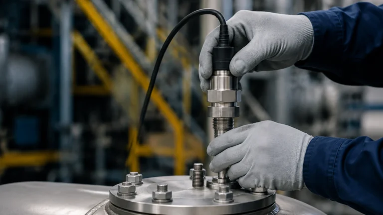
In closed tanks or pressurized vessels, the level of a liquid cannot be determined by a single pressure sensor because the gas pressure above the liquid adds to the total pressure at the bottom. To isolate the liquid level, a differential pressure transmitter is used.
The principle is based on the hydrostatic equation:
ΔP = ρgh
Where:
* ΔP is the differential pressure (the difference between the high-pressure side at the bottom and the low-pressure side at the top).
* ρ (Rho) is the density of the fluid.
* g is the acceleration due to gravity.
* h is the height of the liquid column.
By measuring the pressure at the bottom of the tank (High Side) and subtracting the gas pressure at the top (Low Side), the instrument calculates the exact height of the liquid, regardless of the internal vessel pressure.
2. Dual-Sensor Subtraction Principle
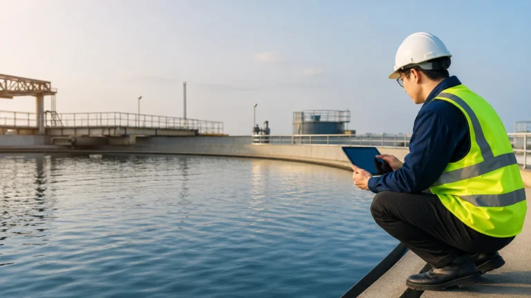
In open-channel applications, such as water intake screens at a power plant or wastewater treatment facility, differential level refers to the difference in water height before and after a mechanical screen. As debris accumulates on the screen, the water level upstream rises while the level downstream falls or remains constant.
This is achieved using two independent sensors (typically ultrasonic or radar) and a controller. The controller receives signals from both sensors and performs the calculation:
Differential Level = Level (Upstream) – Level (Downstream)
When the differential reaches a pre-set threshold, the controller triggers a cleaning mechanism (like a trash rake) to clear the obstruction.
Key Technologies for Differential Level Measurement
Choosing the right instrument requires an understanding of the media and the environment. As a professional manufacturer, Welk provides various instruments that can be configured for these tasks. You can Review product options and application support on our Main Page to see specific hardware configurations.
Radar Level Meters
Radar sensors use Frequency Modulated Continuous Wave (FMCW) or pulse technology. They are ideal for dual-sensor differential applications where accuracy is paramount. Because radar is non-contact and unaffected by air temperature, steam, or dust, it is the preferred choice for outdoor intake screens or volatile chemical tanks.
Ultrasonic Level Sensors
Ultrasonic sensors are the standard for water and wastewater differential level applications. They are cost-effective and provide reliable non-contact measurement. However, they can be sensitive to heavy foam, extreme wind, or significant temperature gradients between the sensor and the liquid surface.
Hydrostatic Level Transmitters
For applications where non-contact sensors cannot be mounted (due to physical space constraints), submersible hydrostatic sensors can be placed on either side of a barrier. These measure the pressure exerted by the liquid column and convert it to a level signal. They are robust but require regular cleaning if the media contains high solids.
Selection Criteria for Differential Level Systems
Selecting the appropriate system involves evaluating the physical properties of the process and the desired control outcome. The following table provides a comparison of common technologies used in differential level applications.
Technology Selection Table
| Feature | DP Transmitter (Capillary/Impulse) | Dual Ultrasonic Sensors | Dual Radar Sensors |
| :— | :— | :— | :— |
| Application Type | Pressurized Vessels | Open Channels / Screens | Open Channels / Chemical Tanks |
| Measurement Range | Up to 40m (Pressure dependent) | 0.1m to 15m | 0.1m to 100m |
| Accuracy | High (±0.075% to 0.1% span) | Moderate (±0.25% of range) | Very High (±1mm to ±3mm) |
| Media Contact | Yes (via diaphragm/impulse) | No | No |
| Effect of Steam/Vapor | None | Significant | Minimal |
| Maintenance Needs | Moderate (Cleaning lines) | Low | Very Low |
| Cost | Mid-Range | Economical | Premium |
Practical Applications in Industry
1. Screen and Filter Control
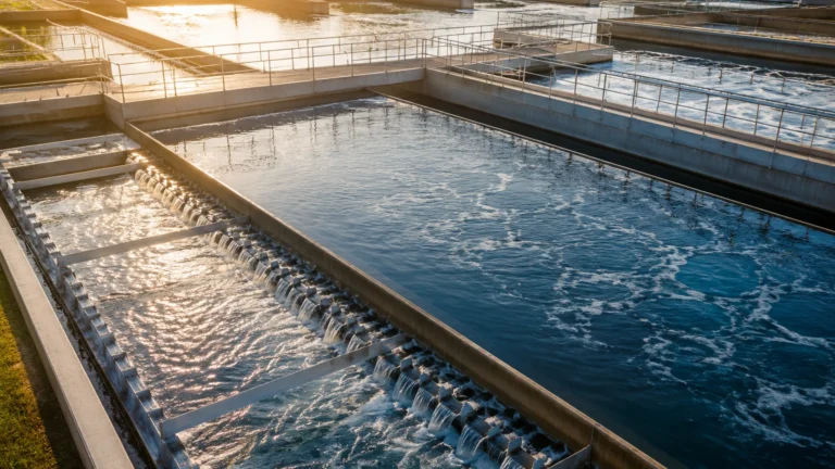
In municipal water treatment, bar screens prevent large debris from entering sensitive equipment. If the differential level across the screen becomes too high, the screen could collapse, or the pumps downstream could cavitate due to lack of flow. A differential level system automates the cleaning cycle, ensuring the screen is only cleaned when necessary, which reduces mechanical wear.
2. Pressurized Storage Tanks
In the oil and gas industry, tanks containing liquefied gases (like LPG or LNG) operate under high pressure. A standard level gauge would be crushed or provide false readings. A differential pressure transmitter with remote seals allows for the measurement of the liquid level while compensating for the high-pressure blanket of gas above the liquid.
3. Hydroelectric Head Monitoring
Hydroelectric dams monitor the differential level between the forebay (upstream) and the tailrace (downstream). This "head" measurement is used to calculate the potential power output and to manage water release through the turbines.
Installation Considerations
To ensure the accuracy of a differential level system, several installation factors must be addressed:
* Sensor Alignment: In dual-sensor setups, both sensors must be calibrated to the same zero-datum point. If the upstream sensor is mounted 100mm higher than the downstream sensor, this offset must be programmed into the controller.
* Stilling Wells: In turbulent water, such as near a dam gate or a high-flow intake, sensors should be installed inside a stilling well (a vertical pipe with a small opening at the bottom). This dampens surface ripples and prevents erratic readings.
* Impulse Line Sloping: For DP transmitters using impulse lines, the lines must be sloped (typically 1:12) to allow gas bubbles to vent back into the tank (for liquid lines) or condensate to drain (for gas lines).
* Temperature Compensation: Since the speed of sound changes with air temperature, ultrasonic sensors must have integrated temperature compensation to maintain accuracy in outdoor differential level applications.
Limitations and Risks
While differential level measurement is highly effective, there are inherent risks to consider:
1. Density Variations: DP-based level measurement assumes a constant fluid density. If the temperature of the liquid fluctuates significantly, the density changes, leading to a "density error" in the level calculation. In such cases, a multivariable transmitter that compensates for temperature is required.
2. Sensor Fouling: In wastewater applications, grease and debris can coat the face of an ultrasonic transducer or the diaphragm of a hydrostatic sensor. Regular maintenance schedules are necessary to prevent signal loss.
3. Mounting Obstructions: For radar and ultrasonic sensors, internal tank structures like ladders, agitators, or pipes can create "false echoes." Advanced software masking is required to ignore these fixed obstructions.
Frequently Asked Questions (FAQs)
Q: Can I use two different types of sensors for differential level?
A: While possible, it is not recommended. Different sensors (e.g., one radar and one ultrasonic) have different response times and accuracy profiles, which can lead to "chatter" or inaccuracies in the differential calculation. It is best to use a matched pair.
Q: What is the maximum distance between sensors in a dual-sensor system?
A: Modern controllers can often handle sensors located hundreds of meters apart, provided the signal (typically 4-20mA or RS485) is shielded properly to prevent electromagnetic interference.
Q: How do I handle foam in a differential level application?
A: Foam can absorb ultrasonic signals, leading to a "Lost Echo" error. In foamy environments, 80GHz high-frequency radar is the superior choice as it penetrates foam much more effectively than ultrasonic waves.
Conclusion
Differential level measurement is a cornerstone of efficient industrial operations, providing the data necessary to automate cleaning cycles and protect high-value assets. Whether utilizing the precision of radar or the rugged reliability of hydrostatic pressure, selecting the right technology requires a deep understanding of the specific process conditions.
For engineers looking to specify a system, it is vital to confirm the chemical compatibility of the wetted parts, the expected range of the differential, and the environmental conditions at the installation site. For further technical specifications and to explore our full range of measurement hardware, please visit our Main Page.