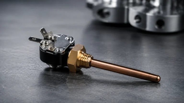
Flowfit Cya21
Flowfit Cya21
In industrial process control, the accuracy of liquid analysis is as critical as the precision of volume and level monitoring. The Flowfit CYA21 is a modular flow assembly designed specifically for the bypass installation of sensors in water and wastewater applications. While level measurement instruments, such as those found on the Main Page of industrial instrumentation providers, manage the physical quantity of a medium, flow assemblies like the CYA21 ensure that the chemical and physical properties of that medium are measured under stable, controlled conditions.
This article provides a comprehensive technical overview of the Flowfit CYA21, its measurement principles, selection criteria, and its role alongside level measurement technologies in integrated process automation.
Understanding the Flow-Through Measurement Principle
Before selecting a flow assembly, it is essential to understand the hydrodynamic principles that govern its operation. Analytical sensors, such as those for pH, oxidation-reduction potential (ORP), conductivity, or dissolved oxygen, often require a specific environment to provide reliable data. Direct immersion into large tanks or high-velocity main pipes can subject sensors to mechanical stress, turbulence, or representative sampling errors.
The Bypass Mechanism
The Flowfit CYA21 operates on the bypass principle. A portion of the process liquid is diverted from the main transport pipe into the assembly. The internal geometry of the CYA21 is engineered to maintain a constant flow velocity across the sensor membrane or electrode. This controlled flow serves three primary purposes:
1. Response Time Optimization: By ensuring a continuous exchange of the medium, the sensor always interacts with the most current process liquid, minimizing measurement lag.
2. Self-Cleaning Effect: A steady flow helps prevent the accumulation of biofilms or suspended solids on the sensor surface, which is a common cause of drift in wastewater applications.
3. Sensor Protection: The assembly acts as a buffer against sudden pressure surges or large debris found in the main process line.
Hydrodynamic Design
The assembly is designed to minimize dead zones where liquid could stagnate. Stagnation leads to inaccurate readings that do not reflect the actual state of the process. The CYA21 utilizes a modular design that allows for the adjustment of the flow path based on the specific sensor type installed, ensuring that the sensitive tip of the probe is positioned in the optimal flow stream.
Technical Specifications and Material Selection
The durability of a flow assembly depends entirely on its material compatibility with the process medium. The Flowfit CYA21 is typically offered in various plastic and metallic configurations to suit different chemical environments.
Material Comparison Table
| Material | Temperature Range | Pressure Rating (at 20°C) | Typical Applications |
| :— | :— | :— | :— |
| PVC (Polyvinyl Chloride) | 0 to 50°C (32 to 122°F) | 6 bar (87 psi) | Standard water treatment, swimming pools |
| PVDF (Polyvinylidene Fluoride) | -20 to 100°C (-4 to 212°F) | 10 bar (145 psi) | Aggressive chemicals, demineralized water |
| Stainless Steel (316L) | -20 to 150°C (-4 to 302°F) | 16 bar (232 psi) | High-pressure industrial processes, hot water |
Modular Configurations
The CYA21 is characterized by its modularity. It can accommodate up to three sensors simultaneously, allowing for multi-parameter measurement (e.g., pH, ORP, and temperature) in a single compact unit. This reduces the number of pipe penetrations required and simplifies the overall piping and instrumentation diagram (P&ID).
Selection Criteria for Industrial Applications
Choosing the correct configuration of the Flowfit CYA21 requires an evaluation of several process parameters. Engineers must look beyond the sensor type and consider the physical environment of the installation.
1. Flow Rate Requirements
For most analytical sensors within the CYA21, a minimum flow rate of approximately 5 liters per hour (l/h) is required to ensure a representative sample. However, excessive flow (above 100 l/h) can cause venturi effects or mechanical vibration that may damage delicate glass electrodes. The use of a flow switch or a rotameter in series with the assembly is recommended to monitor these conditions.
2. Chemical Compatibility
In chemical dosing or industrial wastewater treatment, the pH levels can fluctuate significantly. While PVC is cost-effective for neutral water, PVDF is mandatory for processes involving strong acids or oxidizing agents. If the process involves organic solvents, stainless steel or specialized fluoropolymers must be evaluated.
3. Integration with Level Control
In many B2B applications, the flow assembly is part of a larger feedback loop. For example, in a neutralization tank, a radar level meter or ultrasonic sensor monitors the volume of the tank to prevent overflow, while the CYA21 monitors the pH of the effluent. If the level sensor indicates the tank is nearly empty, the flow through the bypass may drop, potentially leading to dry-running of the analytical sensors. Understanding this relationship is vital for programming PLC logic. For more information on selecting the level measurement component of this system, users can Review product options and application support.
Installation Considerations and Best Practices
Proper installation is the most significant factor in the longevity and accuracy of a flow assembly system. Incorrect positioning can lead to air entrapment or sediment buildup.
Orientation and Positioning
* Vertical Installation: The Flowfit CYA21 should ideally be installed vertically. The inlet should be at the bottom and the outlet at the top. This configuration ensures that the assembly remains completely filled with liquid and allows any air bubbles to escape naturally through the top.
* Bypass Line Sizing: The bypass piping should generally be smaller than the main process line (typically 12mm to 25mm or 1/2" to 1") to maintain sufficient pressure to drive the flow through the assembly.
* Isolation Valves: Install manual ball valves both upstream and downstream of the assembly. This allows for sensor calibration and maintenance without shutting down the main process line.
Pressure and Temperature Compensation
Since the CYA21 is often used in pressurized systems, it is important to note that the pressure rating of the assembly decreases as the temperature increases. For example, a PVC assembly rated for 6 bar at 20°C may only be rated for 2 bar at 50°C. Always refer to the pressure-temperature de-rating curves provided in the technical data sheet.

Potential Risks and Limitations
While the Flowfit CYA21 is a robust solution, it is not suitable for every application. Engineers should be aware of the following limitations:
* High Solids Content: In applications with high concentrations of suspended solids (e.g., primary sewage or thick sludges), the narrow channels within the assembly can clog. In such cases, immersion-style assemblies or self-cleaning bypass systems are preferred.
* Air Entrainment: If the process liquid is prone to foaming or contains significant dissolved gases that may break out of solution, the resulting bubbles can coat the sensor membrane, leading to erratic readings or "flat-lining" of the signal.
* Pressure Drops: The assembly introduces a small amount of head loss into the bypass line. If the differential pressure between the take-off point and the return point is too low, the flow rate may be insufficient for accurate measurement.
Maintenance and Calibration Procedures
A primary advantage of the CYA21 is the ease of maintenance. Because the sensors are housed in a bypass, they can be accessed frequently for cleaning and calibration.
1. Sensor Cleaning: Depending on the medium, sensors should be removed and cleaned with appropriate solutions (e.g., dilute HCl for calcium deposits or surfactants for oily residues) on a weekly or monthly basis.
2. O-Ring Inspection: The seals within the assembly are wear parts. They should be inspected for brittleness or swelling during every sensor calibration and replaced annually to prevent leaks.
3. Flow Verification: Periodically check the inlet and outlet ports for any accumulation of debris that might restrict flow.
Frequently Asked Questions (FAQ)
Q: Can the Flowfit CYA21 be used for potable water applications?
A: Yes, provided the materials selected (such as PVC or Stainless Steel) meet local regulatory requirements for drinking water contact. The assembly is widely used for monitoring chlorine and pH in municipal water systems.
Q: How do I handle a situation where the main pipe pressure is too high for the assembly?
A: A pressure-reducing valve should be installed on the bypass line before the inlet of the CYA21. Additionally, ensure the return line is directed to a low-pressure point, such as an atmospheric tank or the suction side of a pump.
Q: Can I install different brands of sensors in the CYA21?
A: The CYA21 is designed with standard threads (typically Pg 13.5), which is the industry standard for most analytical probes. This allows for significant flexibility in sensor selection, though compatibility with the specific cable glands and immersion depth must be verified.
Q: What is the impact of flow velocity on sensor life?
A: Constant, moderate flow actually extends the life of many sensors by preventing the buildup of contaminants. However, extremely high velocity can cause "leaching" of the reference electrolyte in pH probes, shortening their lifespan. Maintaining the flow within the recommended 5-100 l/h range is ideal.
Conclusion
The Flowfit CYA21 serves as a vital interface between the process liquid and the analytical instrumentation. By providing a stable, modular environment for sensors, it ensures that data regarding water quality is as reliable as the data regarding tank volumes provided by high-quality level meters. For engineers designing comprehensive monitoring systems, integrating reliable flow assemblies with advanced level measurement solutions is the key to achieving efficient and automated process control. For further technical specifications on level measurement instruments that complement these flow assemblies, please visit the Main Page for detailed product catalogs and engineering support.