Flowrate Sensor
Flowrate Sensor
In the landscape of industrial process control, the flowrate sensor stands as a fundamental instrument for monitoring the movement of liquids, gases, and steam through piping systems and open channels. Understanding the volume or mass of a medium passing a specific point per unit of time is critical for billing, process efficiency, safety, and chemical dosing. While Welk is widely recognized for its expertise in level measurement, the principles of level and flow are often inextricably linked, particularly in environmental monitoring and bulk fluid management.
Selecting the appropriate flowrate sensor requires a deep understanding of fluid dynamics, the physical properties of the medium, and the specific constraints of the installation site. This guide explores the primary measurement principles, selection criteria, and practical engineering considerations for deploying flowrate sensors in industrial environments.
Core Measurement Principles
Before selecting a flowrate sensor, engineers must understand the physical laws that govern different measurement technologies. Flow measurement is generally categorized into volumetric flow and mass flow.
Electromagnetic Flow Measurement
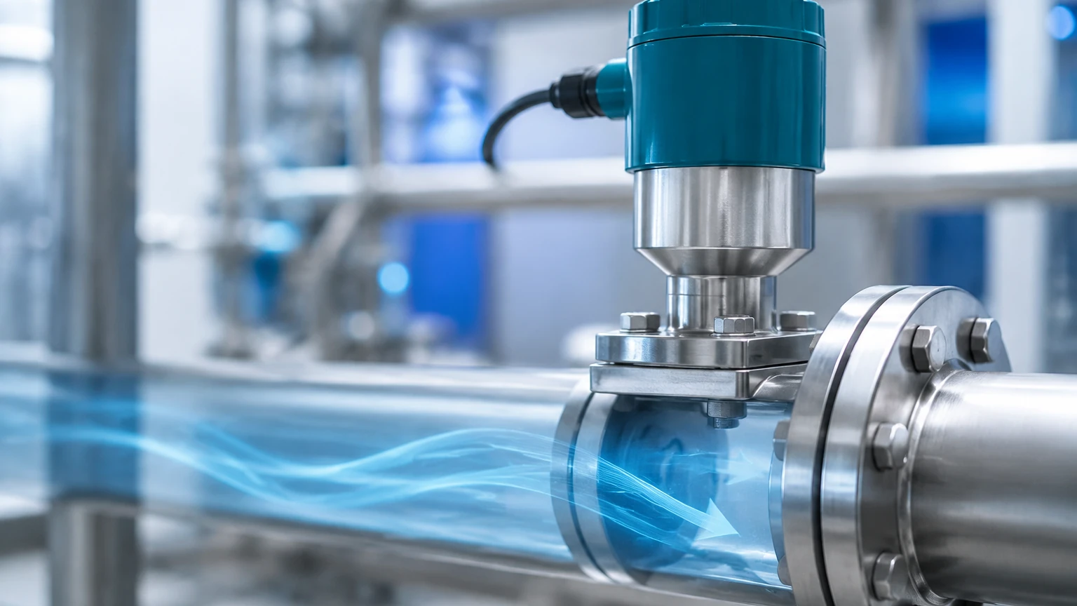
Electromagnetic flowmeters operate based on Faraday’s Law of Electromagnetic Induction. When a conductive liquid flows through a magnetic field generated by the sensor, it produces a voltage. This voltage is directly proportional to the velocity of the liquid. Since the cross-sectional area of the pipe is known, the sensor calculates the volumetric flowrate.
* Requirement: The fluid must have a minimum electrical conductivity (typically >5 μS/cm).
* Advantage: No moving parts and no pressure drop.
Ultrasonic Flow Measurement
Ultrasonic sensors use sound waves to determine flow velocity. There are two primary types:
1. Transit-Time: Two transducers send and receive ultrasonic signals. The difference in time taken for the signal to travel upstream versus downstream is proportional to the flow velocity. This is ideal for clean liquids.
2. Doppler: These sensors measure the frequency shift of ultrasonic signals reflected off particles or bubbles in the fluid. This is best suited for slurries or aerated liquids.
Vortex Flow Measurement
Vortex sensors utilize the Karman Vortex Street principle. As fluid flows past a bluff body (a non-streamlined object) placed in the flow stream, vortices are shed alternately on each side. The frequency of this vortex shedding is directly proportional to the fluid velocity. These are highly versatile and can measure liquids, gases, and steam.
Turbine Flow Measurement
Turbine flowmeters use the mechanical energy of the fluid to rotate a rotor within the flow stream. The rotational speed of the rotor is proportional to the velocity of the fluid. These sensors are valued for their high accuracy in clean, low-viscosity fluids.
Differential Pressure (DP) Measurement
DP flowmeters create a constriction in the pipe (such as an orifice plate or Venturi tube) to cause a pressure drop. According to Bernoulli’s equation, the square root of the pressure difference between the upstream and downstream sides is proportional to the flowrate.
The Relationship Between Level and Flow
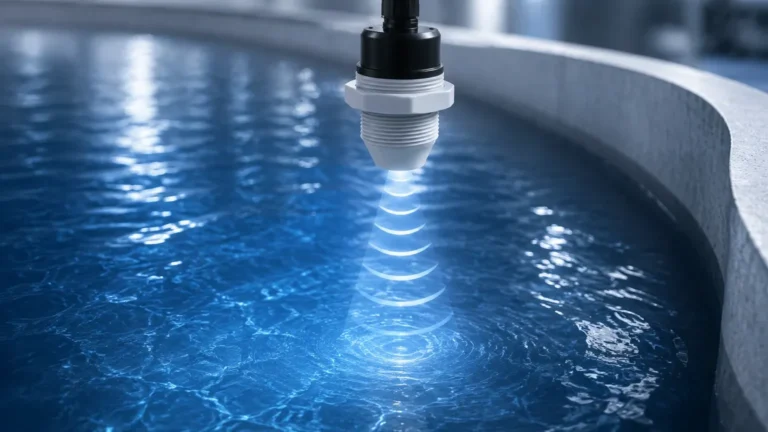
In many B2B applications, particularly in water treatment and irrigation, flow is measured in open channels rather than closed pipes. In these scenarios, a flowrate sensor system often utilizes a level measurement device, such as those found on our Main Page, in conjunction with a primary flow element like a flume or weir.
By measuring the "head" (the height of the liquid) behind the constriction, the flowrate can be calculated using standardized mathematical formulas (e.g., the Manning formula or specific weir equations). Welk’s ultrasonic and radar level meters are frequently used as the primary sensing component in these flowrate sensor assemblies due to their non-contact nature and high precision.
Industrial Selection Criteria
Choosing the right sensor involves balancing technical requirements with budget constraints. The following table provides a comparison of common flowrate sensor technologies.
| Technology | Typical Media | Accuracy (Typical) | Conductivity Required | Pressure Drop | Moving Parts |
| :— | :— | :— | :— | :— | :— |
| Electromagnetic | Conductive Liquids | ±0.5% | Yes | None | No |
| Ultrasonic | Clean/Dirty Liquids | ±1.0% | No | None | No |
| Vortex | Liquid, Gas, Steam | ±1.0% | No | Low | No |
| Turbine | Clean Liquids/Gases | ±0.25% | No | Medium | Yes |
| Differential Pressure | All Media | ±1.0% to ±2.0% | No | High | No |
Key Evaluation Factors
1. Fluid Properties: Is the medium corrosive, abrasive, or viscous? For example, electromagnetic sensors are excellent for corrosive acids but require a conductive medium.
2. Flow Profile: Most sensors require a fully developed flow profile. This means having sufficient straight pipe runs (typically 10x pipe diameter upstream and 5x downstream) to avoid turbulence caused by elbows or valves.
3. Operating Conditions: Ensure the sensor body and liners can withstand the maximum process temperature and pressure. For high-temperature steam, vortex or DP meters are standard.
4. Turndown Ratio: This is the ratio of the maximum flow to the minimum flow that the sensor can accurately measure. If your process has highly variable flow, a high turndown ratio (like that of ultrasonic or electromagnetic meters) is essential.
Installation Considerations and Best Practices
Proper installation is as critical as sensor selection. Even the most advanced flowrate sensor will provide inaccurate data if installed incorrectly.
* Pipe Orientation: For liquid applications, sensors should ideally be installed in vertical pipes with upward flow. This ensures the pipe is always full and prevents air pockets from interfering with the measurement. If horizontal installation is necessary, the sensor should not be placed at the highest point of the system where air collects.
* Grounding: Electromagnetic sensors are sensitive to electrical noise. Proper grounding to the process liquid is mandatory to ensure a stable signal.
* Straight Runs: To eliminate swirl and turbulence, adhere strictly to the manufacturer's requirements for straight pipe lengths. If space is limited, flow conditioners or rectifiers may be required.
* Accessibility: Sensors should be installed where they can be accessed for calibration and maintenance. Even "maintenance-free" non-contact sensors like ultrasonic clamp-on models require periodic signal checks.
Limitations and Common Risks
Engineers must be aware of the inherent limitations of flowrate sensor technologies to avoid premature failure or data errors.
1. Cavitation: In liquid flows, if the local pressure drops below the vapor pressure, bubbles form and collapse. This can damage turbine blades and cause significant errors in ultrasonic and vortex measurements.
2. Scaling and Coating: In wastewater or chemical processing, material can build up on the internal walls of the sensor or on electrodes. This changes the cross-sectional area or insulates the electrodes, leading to drift. Radar-based level sensors used for open-channel flow are less susceptible to this as they do not touch the medium.
3. Minimum Flow Velocity: Many sensors have a "low-flow cutoff." If the velocity is too low, the signal-to-noise ratio becomes too poor to provide a reliable reading. This is common with vortex and turbine meters.
4. Environmental Interference: External vibrations can interfere with vortex sensors, while high-frequency electrical noise can affect electromagnetic and ultrasonic signal processing.
Frequently Asked Questions (FAQ)
Q: Can I use a flowrate sensor for both water and oil?
A: It depends on the technology. An electromagnetic meter will work for water but not for oil (which is non-conductive). An ultrasonic or turbine meter can work for both, provided the viscosity of the oil is within the sensor's operating range.
Q: What is the difference between a flow sensor and a flow meter?
A: In technical terms, the "sensor" is the primary element that detects the flow, while the "meter" includes the transmitter and display that converts the sensor signal into a readable flow value. In common B2B parlance, the terms are often used interchangeably.
Q: How often should a flowrate sensor be calibrated?
A: Calibration frequency depends on the criticality of the process and the type of sensor. Mechanical meters (turbine) usually require more frequent calibration due to wear. Many industrial standards suggest an annual calibration check, though some stable technologies like electromagnetic meters may go longer in clean applications.
Q: Are clamp-on ultrasonic sensors as accurate as inline sensors?
A: Generally, high-quality inline sensors are more accurate because the internal diameter and pipe wall characteristics are factory-calibrated. However, modern clamp-on sensors offer excellent repeatability and are often the only practical solution for retrofitting existing large-diameter pipes.
Conclusion
Selecting a flowrate sensor is an exercise in matching technology to the specific nuances of a process. Whether you are measuring the flow of cooling water in a power plant or monitoring chemical discharge in a treatment facility, the accuracy of your data depends on a rigorous evaluation of fluid dynamics and installation environment. For those integrating flow systems with comprehensive level monitoring, reviewing technical specifications on our Main Page can provide further insight into how these instruments work in tandem to optimize industrial automation. By adhering to established engineering principles and considering the limitations of each technology, facilities can ensure long-term reliability and process efficiency.