Flowsic 600
Flowsic 600
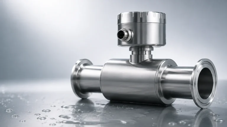
In the complex landscape of industrial process control, the measurement of gas flow requires a high degree of precision, particularly in custody transfer and high-value process applications. The FLOWSIC 600 is an ultrasonic gas flow meter designed to meet these rigorous demands. While many industrial facilities focus heavily on liquid level measurement, the integration of precise flow data is essential for mass balance, leak detection, and overall system efficiency. This guide examines the technical foundations, application criteria, and installation requirements for the FLOWSIC 600, providing engineers with a practical reference for integrating this technology into broader automation frameworks.
Measurement Principle: Ultrasonic Transit-Time Technology
Before evaluating the specific features of the FLOWSIC 600, it is essential to understand the underlying physics of ultrasonic flow measurement. The device utilizes the transit-time difference principle.
The Physics of Transit Time
Ultrasonic transducers are mounted on the meter body, positioned to send and receive acoustic pulses diagonally across the gas stream. When gas is flowing through the pipe, a pulse traveling in the direction of the flow (downstream) moves faster than a pulse traveling against the flow (upstream).
The meter calculates the time difference between these two pulses. This difference is directly proportional to the average velocity of the gas. By knowing the cross-sectional area of the meter body and the velocity of the gas, the device calculates the actual volume flow rate.
Multi-Path Configuration
One of the defining characteristics of the FLOWSIC 600 is its multi-path design. A single-path meter is highly sensitive to flow profile disturbances (such as turbulence caused by elbows or valves). To mitigate this, the FLOWSIC 600 typically employs four or more acoustic paths. These paths are arranged in a chordal configuration, allowing the meter to sample the velocity at different points across the pipe diameter. This spatial averaging ensures high accuracy even in non-ideal flow conditions and provides the redundancy required for custody transfer applications.
Key Features and Evaluation Criteria
When selecting a gas flow meter, engineers must weigh the FLOWSIC 600 against other technologies like turbine meters or orifice plates. The FLOWSIC 600 offers several distinct advantages that influence the total cost of ownership and long-term reliability.
Accuracy and Rangeability
The FLOWSIC 600 is known for its wide turndown ratio, often exceeding 100:1. Unlike mechanical meters, which have a minimum flow threshold to overcome friction, ultrasonic meters can detect very low velocities. In custody transfer configurations, the meter typically achieves an accuracy of ±0.1% to ±0.2% after flow calibration. For process applications, an uncalibrated accuracy of ±0.5% is common.
Non-Intrusive Design
Because the ultrasonic transducers are typically mounted flush with the internal wall of the pipe, there are no moving parts or obstructions in the flow path. This results in zero pressure drop across the meter, which is a significant factor in reducing energy costs in high-volume gas transport. Furthermore, the absence of moving parts reduces mechanical wear, extending the maintenance interval compared to turbine meters.
Advanced Diagnostics
The electronic suite of the FLOWSIC 600 provides real-time diagnostics. It monitors the "signal-to-noise ratio" and the "gain" of each acoustic path. If a path begins to fail due to contamination or electronic drift, the system alerts the operator. This predictive maintenance capability is a core component of modern industrial automation, ensuring that the meter remains within its performance envelope between scheduled calibrations.
Technical Selection Table
The following table outlines the general specifications for the FLOWSIC 600 series to assist in the initial selection process.
| Feature | Specification (Standard) | Specification (High-Pressure/Special) |
| :— | :— | :— |
| Nominal Pipe Size | DN50 to DN1200 (2" to 48") | Custom sizes up to DN1800 |
| Operating Pressure | 0 to 280 bar (4,060 psi) | Up to 450 bar (6,526 psi) |
| Gas Temperature | -40°C to +180°C | -194°C (Cryogenic) to +280°C |
| Accuracy | ±0.1% to ±0.5% | Dependent on path configuration |
| Enclosure Rating | IP66 / NEMA 4X | ATEX/IECEx certified for Zone 1 |
| Body Materials | Carbon Steel, Stainless Steel | Duplex, Low-temp Steel |
Integration with Level Measurement Systems
In many industrial environments, such as oil and gas separators or chemical storage facilities, gas flow measurement is used in tandem with liquid level measurement. For instance, in a separator vessel, monitoring the gas outflow with a FLOWSIC 600 while simultaneously tracking the liquid level with a radar level meter or magnetic level gauge is critical for process stability. Accurate level data ensures that liquid does not carry over into the gas line, which could damage flow instrumentation or downstream compressors.
For engineers looking to harmonize their flow data with reliable level instrumentation, exploring a comprehensive range of sensors is necessary. You can Review product options and application support to find level measurement solutions that complement high-precision flow meters like the FLOWSIC 600. Integrating these technologies onto a single automation platform allows for more precise mass balance calculations and improved safety protocols.
Installation Considerations
The performance of an ultrasonic flow meter is heavily dependent on the quality of the installation. Even the most advanced meter will fail to meet its accuracy specifications if the flow profile is distorted.
Straight Pipe Requirements
To ensure a fully developed and stable flow profile, the FLOWSIC 600 requires a specific length of straight pipe upstream and downstream.
1. Upstream: Typically 10 to 20 times the nominal pipe diameter (10D to 20D) depending on the presence of bends or headers.
2. Downstream: Typically 3 to 5 times the nominal pipe diameter (3D to 5D).
If the available footprint is limited, a flow conditioner (such as a perforated plate) can be installed upstream to shorten the required straight run. However, flow conditioners introduce a small pressure drop, which must be factored into the system design.
Orientation and Mounting
The meter should be installed in a position where gas remains in a single phase. In applications where liquid condensation is possible, the meter should be installed in a vertical run with upward flow, or the transducers should be positioned at an angle (e.g., 3 o'clock and 9 o'clock) to prevent moisture from pooling in the transducer ports.
Electrical and Signal Integrity
Given that ultrasonic signals are low-voltage high-frequency pulses, they are susceptible to electromagnetic interference (EMI). Shielded cabling and proper grounding are mandatory. The electronics should be mounted in a location that is accessible for maintenance but protected from extreme vibration, which can affect the ultrasonic signal processing.

Common Risks and Limitations
While the FLOWSIC 600 is a robust instrument, certain conditions can compromise its performance.
* Ultrasonic Noise: Control valves located near the meter can generate high-frequency noise that overlaps with the ultrasonic frequency of the transducers. This "acoustic noise" can drown out the measurement signal. High-frequency noise-attenuating valves or increased distance between the valve and the meter are common solutions.
* Contamination: While the meter has no moving parts, heavy buildup of paraffin, hydrates, or compressor oil on the transducer faces can attenuate the signal. Regular diagnostic checks should be used to monitor signal strength.
* Gas Composition: Ultrasonic meters calculate the speed of sound in the medium as a diagnostic check. If the gas composition changes significantly (e.g., a shift in the percentage of CO2 or N2), the expected speed of sound will change. The meter must be programmed with the correct gas properties to maintain its diagnostic integrity.
Maintenance and Calibration
One of the primary B2B advantages of the FLOWSIC 600 is its long-term stability. However, for regulated custody transfer, periodic recalibration is required. This is usually performed at a high-pressure flow laboratory using a master meter or a piston prover.
In the field, maintenance is largely focused on:
* Verifying the electronics via internal self-tests.
* Checking the transducer health through signal-to-noise ratios.
* Inspecting the internal bore for corrosion or sediment if the gas is "sour" or "wet."
Frequently Asked Questions (FAQ)
Q: Can the FLOWSIC 600 measure liquids?
A: No, the FLOWSIC 600 is specifically designed for gas phases. For liquid level measurement, technologies such as ultrasonic level sensors or radar transmitters are more appropriate and can be found on the Welk Main Page.
Q: What happens if one ultrasonic path fails?
A: The FLOWSIC 600 is designed with redundancy. If one path fails, the meter will continue to operate using the remaining paths, though the uncertainty (accuracy) may slightly increase. The diagnostic system will trigger an alarm to notify the operator of the path failure.
Q: Is the meter suitable for hydrogen blending?
A: Yes, ultrasonic technology is well-suited for varying gas compositions, including hydrogen. However, because the speed of sound in hydrogen is significantly higher than in natural gas, the transducers and electronics must be configured specifically for the expected gas mixture.
Q: How does temperature affect the measurement?
A: Temperature affects the density and the speed of sound in the gas. The FLOWSIC 600 measures the actual volume flow. To convert this to standard volume (e.g., Nm³ or SCF), an external pressure and temperature transmitter (P&T) and a flow computer are required to perform the compensation.
Conclusion
The FLOWSIC 600 remains a leading choice for high-precision gas flow measurement due to its multi-path accuracy, lack of pressure drop, and sophisticated diagnostics. For industrial operators, successful implementation requires careful attention to upstream piping, gas composition, and the integration of the meter into a broader process control strategy that includes reliable level and pressure monitoring. By adhering to established installation guidelines and utilizing the device's diagnostic capabilities, engineers can ensure long-term measurement reliability in the most demanding gas applications.