Flowsic100 Flare Xt
Flowsic100 Flare Xt
In the complex landscape of industrial emissions monitoring and process safety, flare gas measurement represents one of the most challenging applications for instrumentation. The Flowsic100 Flare XT is a specialized ultrasonic flow measurement system designed specifically to handle the extreme conditions found in flare stacks. While many industrial facilities focus heavily on the flow rates of waste gases for environmental compliance and loss control, the broader management of flare systems requires a multi-faceted approach that includes both flow and level measurement technologies.
Understanding the technical nuances of the Flowsic100 Flare XT, alongside the critical role of level monitoring in flare headers and knock-out drums, is essential for plant engineers and operators. This guide explores the measurement principles, selection criteria, and integration strategies necessary for robust flare system management.
Understanding Ultrasonic Measurement Principles in Flare Applications
To appreciate the capabilities of the Flowsic100 Flare XT, one must first understand the fundamental principles of ultrasonic measurement. In industrial automation, ultrasonic technology is utilized in two primary ways: transit-time flow measurement and pulse-echo level measurement.
Transit-Time Flow Measurement
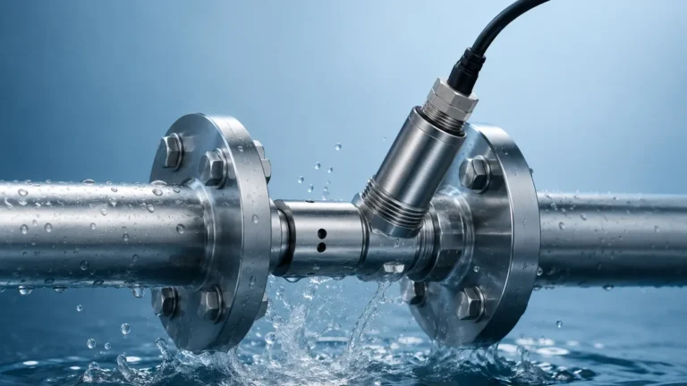
The Flowsic100 Flare XT operates on the transit-time principle. This method involves two ultrasonic transducers mounted across a pipe or stack at an angle. Each transducer can both transmit and receive ultrasonic pulses. When the gas is stationary, the time it takes for a pulse to travel from Transducer A to Transducer B is identical to the time from B to A. However, when gas flows, the pulse traveling with the flow moves faster, and the pulse traveling against the flow moves slower. By measuring this infinitesimal time difference (delta-t), the system calculates the flow velocity with high precision.
Comparison with Level Measurement Principles
In contrast, ultrasonic level sensors—such as those offered by Main Page—utilize the pulse-echo or "time-of-flight" principle. Here, a single transducer emits a sound wave that travels through the air (or gas) space, reflects off the surface of a liquid or solid, and returns to the sensor. The distance is calculated based on the total travel time and the speed of sound in the medium.
While both technologies rely on ultrasonic waves, flare flow meters must account for varying gas compositions and high velocities, whereas level meters must account for surface turbulence and vapor layers. In a flare system, these technologies are often complementary; flow meters track the gas exiting the stack, while level meters monitor the liquid levels in knock-out drums (KOD) to ensure that no liquids reach the flare tip.
Key Features and Capabilities of the Flowsic100 Flare XT
The Flowsic100 Flare XT is engineered to overcome the specific hurdles of flare gas monitoring, which include high turn-down ratios, varying gas densities, and potential transducer contamination.
Wide Dynamic Range
Flare systems experience two distinct states: normal operation (low flow/purge) and emergency flaring (high flow). The Flowsic100 Flare XT is designed to measure velocities ranging from less than 0.1 m/s up to 120 m/s. This wide dynamic range ensures that even small leaks in valves can be detected during standby periods, while massive surges can be accurately quantified during process upsets.
Advanced Transducer Technology
The transducers in this system are often hermetically sealed and made from corrosion-resistant materials like titanium. This is vital because flare gas often contains hydrogen sulfide (H2S) and other aggressive chemicals. Some versions of the Flowsic100 Flare XT also feature a retractable mechanism, allowing for the maintenance or replacement of sensors without shutting down the flare line.
Digital Signal Processing
Modern flare meters use sophisticated algorithms to filter out acoustic noise generated by valves or high-velocity gas. The XT series incorporates intelligent signal processing to maintain measurement integrity even when the signal-to-noise ratio is low, which is common during high-turbulence events.
Selection Criteria for Flare Gas Instrumentation
Selecting the right instrumentation for a flare system requires a detailed analysis of the process conditions. Engineers should use the following criteria when evaluating flow and level measurement solutions:
| Criteria | Flowsic100 Flare XT (Flow) | Ultrasonic/Radar (Level) |
| :— | :— | :— |
| Primary Measurement | Gas velocity and volume flow | Liquid or sludge level in KOD |
| Velocity Range | 0.03 m/s to 120 m/s | N/A (Static or fluctuating levels) |
| Gas Composition | Must handle CH4, H2, CO2, H2S mixtures | Must account for vapor density (Radar preferred) |
| Pipe/Vessel Size | 0.1 m to 2.0 m+ diameters | 1 m to 30 m+ vessel heights |
| Accuracy Requirement | Typically ±2% to ±5% of reading | ±1 mm to ±5 mm depending on tech |
When evaluating these systems, it is also important to consider the "turn-down ratio." For flare gas, a ratio of 1000:1 or higher is often required. For level measurement in associated vessels, the focus shifts to "dead zones" (the minimum distance between the sensor and the high-level limit) and the ability to penetrate foam or steam.
Common Risks and Operational Challenges
Operating a flare measurement system involves several inherent risks that can lead to data loss or safety incidents if not properly managed.
1. Liquid Carryover: If the liquid level in a knock-out drum is not monitored accurately using reliable level transmitters, liquid can be carried into the flare header. This can cause "burning rain," where flaming liquid drops from the flare tip, posing a severe fire hazard. This highlights the necessity of integrating Welk’s hydrostatic or radar level transmitters into the safety instrumented system (SIS).
2. Acoustic Noise Interference: High-pressure steam injection (used for smokeless flaring) or nearby control valves can create ultrasonic noise that interferes with the flow meter’s sensors. The Flowsic100 Flare XT addresses this with frequency-hopping and digital filtering, but sensor placement remains critical.
3. Transducer Fouling: Over time, heavy hydrocarbons, soot, or polymers can build up on the transducer faces. While ultrasonic flow meters are generally more resistant to fouling than thermal mass meters, periodic inspection is required. For level measurement in similar environments, non-contact radar is often preferred over ultrasonic sensors to avoid issues with condensation and buildup.
Integrating Flow and Level Measurement in Flare Systems
A holistic flare gas management system does not rely on a single instrument. Instead, it integrates several measurement points to provide a complete picture of the process.
Knock-Out Drum (KOD) Level Control
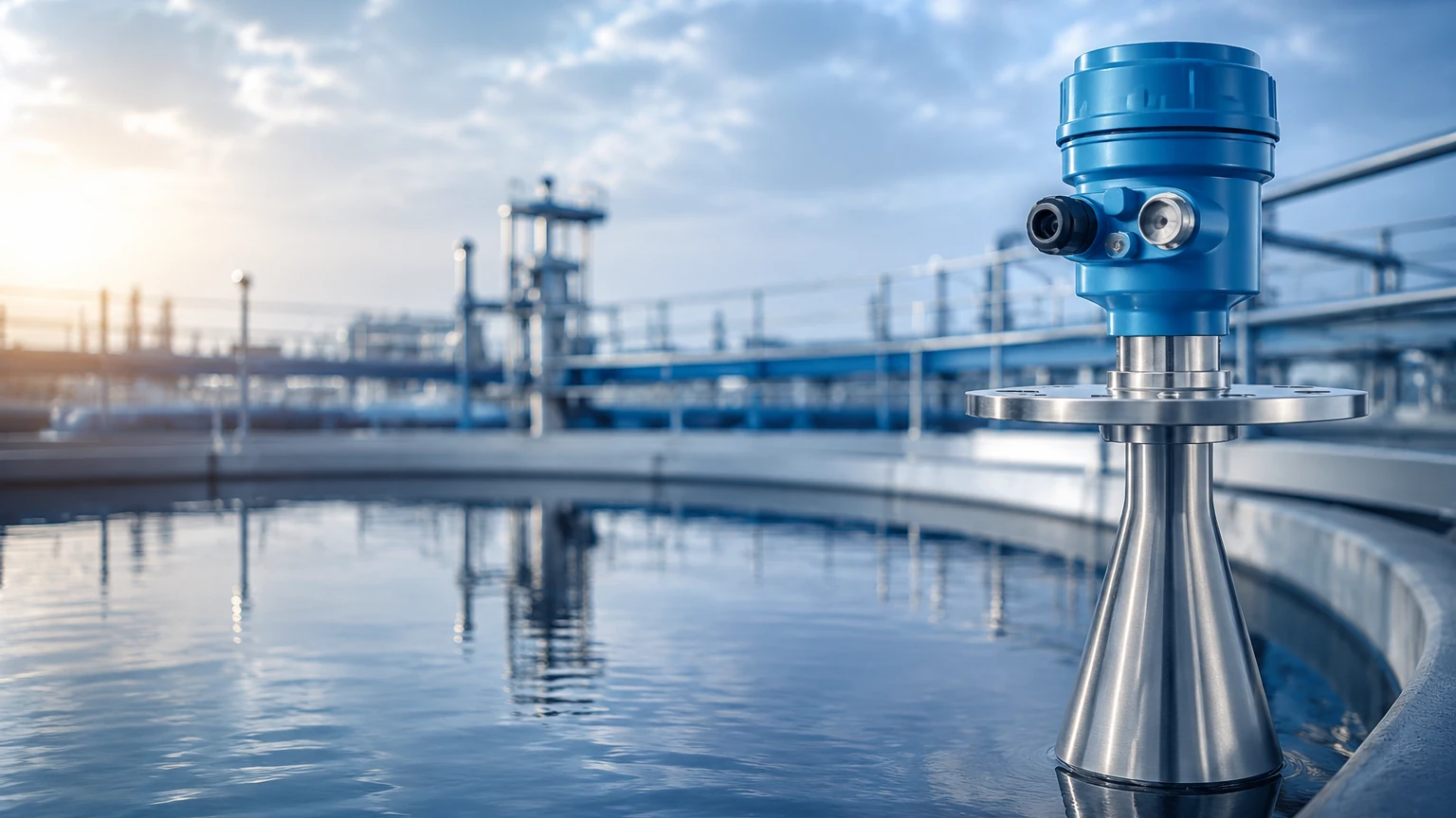
The KOD is the last line of defense before the gas reaches the flare. It is designed to separate liquids from the gas stream. Level measurement here is critical. Radar level meters are frequently used because they are unaffected by the gas composition or pressure changes within the drum. If the level reaches a high-high setpoint, it must trigger an automated pump-out or a process shutdown.
Liquid Seal Drum Monitoring
Many flare systems use a liquid seal drum to prevent backflow of air into the header, which could create an explosive mixture. Monitoring the liquid level in the seal drum ensures the seal is maintained. Hydrostatic level transmitters or magnetic level gauges are often used here due to their reliability in relatively clean liquid applications.
Totalization and Reporting
The data from the Flowsic100 Flare XT is typically fed into a flow computer or a Distributed Control System (DCS). By combining flow data with temperature and pressure measurements, the system can calculate the mass flow and totalize the emissions for regulatory reporting. Integrating level data allows the system to verify that the flow being measured is indeed gas and not a multi-phase mixture.
Installation and Maintenance Best Practices
Proper installation is the single most important factor in the performance of the Flowsic100 Flare XT and associated level instruments.
* Straight Run Requirements: For flow measurement, a minimum of 20 diameters upstream and 10 diameters downstream of straight pipe is generally recommended to ensure a fully developed flow profile. If this is not possible, flow conditioners or multi-path meters may be required.
* Transducer Orientation: In horizontal pipes, transducers should be installed in the 3 o'clock and 9 o'clock positions to prevent them from being submerged in liquid or covered by sediment at the bottom of the pipe.
* Purging Systems: In applications with high concentrations of sticky or corrosive substances, a continuous nitrogen purge can be used to keep the transducer faces clean.
* Calibration Verification: Unlike level meters, which can often be checked with a simple tape measure, flare flow meters require specialized field verification. The Flowsic100 Flare XT includes internal diagnostics that check the "speed of sound" against theoretical values based on gas composition, providing a way to verify accuracy without removing the meter.
Frequently Asked Questions (FAQ)
Q: Can the Flowsic100 Flare XT measure flow in both directions?
A: Yes, ultrasonic transit-time meters are inherently bi-directional. This is useful in systems where gas might migrate back into the header during cooling phases.
Q: Why use ultrasonic technology instead of thermal mass for flare gas?
A: Thermal mass meters are sensitive to gas composition changes (e.g., a shift from methane to hydrogen). Ultrasonic meters measure the speed of sound, which, while also dependent on composition, can be compensated for more effectively in varying flare gas mixtures. Additionally, ultrasonic meters have no probes protruding into the pipe, making them less susceptible to damage from high-velocity debris.
Q: How does gas composition affect level measurement in the KOD?
A: For ultrasonic level meters, changes in gas density or temperature significantly affect the speed of sound, leading to measurement errors. This is why radar level meters, which use electromagnetic waves unaffected by gas properties, are the preferred choice for level measurement in flare system vessels.
Q: What is the maintenance interval for these sensors?
A: In clean gas applications, sensors can operate for several years without intervention. However, in heavy refinery service, a semi-annual inspection of transducer faces and diagnostic data is recommended to ensure long-term reliability.
By carefully selecting and installing advanced flow solutions like the Flowsic100 Flare XT and pairing them with robust level measurement instruments, industrial facilities can achieve high levels of safety, environmental compliance, and process efficiency. For more information on choosing the right level measurement technology for your industrial applications, you can visit the Main Page to explore a wide range of radar, ultrasonic, and magnetic solutions.