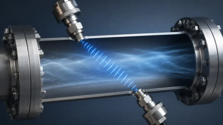
Fluid Level Sensor Fuel
Fluid Level Sensor Fuel
In industrial fuel management, precise measurement is the cornerstone of operational efficiency, safety, and cost control. Whether managing bulk diesel storage for backup generators, monitoring fuel levels in remote mining equipment, or overseeing large-scale aviation fuel depots, the selection of a fluid level sensor fuel system requires a deep understanding of measurement physics and environmental constraints. Fuel, unlike water, presents unique challenges including volatility, temperature-dependent density changes, and stringent hazardous area safety requirements.
This guide examines the primary measurement technologies used for fuel level monitoring, provides selection criteria for engineering teams, and outlines best practices for installation and maintenance.
Measurement Principles for Fuel Level Sensing
Before selecting a specific instrument, it is vital to understand the physical principles that govern how different sensors interact with fuel. Each technology offers distinct advantages depending on the tank geometry and the chemical properties of the fuel.
Hydrostatic Pressure Measurement
Hydrostatic level transmitters measure the pressure exerted by the liquid column above the sensor. The relationship is defined by the formula: $P = \rho \cdot g \cdot h$, where $P$ is pressure, $\rho$ is the density of the fuel, $g$ is gravity, and $h$ is the height of the fluid.
For fuel applications, hydrostatic sensors are often submersible or externally mounted via a flange at the bottom of the tank. Because fuels like diesel and gasoline have lower densities than water (typically 0.70 to 0.85 kg/L), the sensor must be calibrated to the specific gravity of the media. A significant advantage of this method is its reliability in deep tanks and its relative immunity to surface foam.
Capacitive Level Sensing
Capacitive sensors treat the fuel and the air space in the tank as dielectric materials between two conductors (the sensor probe and the tank wall, or two parallel probes). As the fuel level rises, the total capacitance of the system changes because the dielectric constant of fuel (typically 2.0 to 2.2) is higher than that of air (1.0).
This technology is highly effective for continuous monitoring in smaller tanks or vehicle fuel systems. However, it requires recalibration if the fuel type changes significantly, as different fuel blends (such as biodiesel or ethanol-blended gasoline) have different dielectric constants.
Ultrasonic (Non-Contact)
Ultrasonic sensors emit high-frequency sound pulses that reflect off the fuel surface. The sensor measures the time-of-flight (ToF) to calculate the distance. While cost-effective and easy to install, ultrasonic sensors can struggle in fuel tanks where heavy vapors are present. Fuel vapors can change the speed of sound in the air space, leading to measurement errors unless the sensor includes temperature and vapor compensation.
Radar Level Measurement (FMCW and Pulse)
Radar sensors use electromagnetic waves rather than sound. They are generally considered the gold standard for high-precision fuel measurement. Radar waves are unaffected by vapors, pressure, or temperature fluctuations in the tank headspace.
* Guided Wave Radar (GWR): Uses a probe to guide the signal. Excellent for low-dielectric fuels and turbulent surfaces.
* Non-Contact Radar: Uses 26GHz or 80GHz frequencies to bounce signals off the surface. The 80GHz variants are particularly effective for fuel because their narrow beam angle avoids internal tank obstructions like baffles or heating coils.
Magnetic Level Gauges
Magnetic gauges utilize a float containing a high-intensity magnet that moves with the fuel level. This float interacts with a visual indicator or a reed-switch transmitter mounted outside the chamber. This provides a fail-safe visual reference that does not require power, which is critical for safety-critical fuel storage.
Technical Selection Criteria
When evaluating a fluid level sensor fuel solution, engineers must balance precision requirements with the physical realities of the installation site. To explore a comprehensive range of industrial instruments, you can visit the Main Page for detailed product specifications.
1. Fuel Type and Dielectric Constant
The dielectric constant ($\\varepsilon_r$) is the most critical chemical property for radar and capacitive sensors. Most hydrocarbon fuels have a low $\\varepsilon_r$ (under 2.5). This requires sensors with high sensitivity to ensure a reliable signal return from the fluid surface.
2. Tank Geometry and Environment
* Underground Storage Tanks (UST): Often require hydrostatic or flexible guided wave radar sensors due to limited overhead clearance.
* Aboveground Storage Tanks (AST): Typically use non-contact radar or magnetic level gauges.
* Mobile Tanks: Require sensors that can handle sloshing and vibration, such as dampened capacitive probes or hydrostatic sensors with heavy-duty housing.
3. Hazardous Area Certifications
Fuel is inherently flammable. Any electronic sensor installed in or near the tank must carry appropriate certifications, such as ATEX, IECEx, or UL/CSA for Class I, Division 1 or 2 areas. Intrinsic safety (Ex ia) is the preferred protection method for fuel level transmitters.
Comparison Table: Fuel Level Technologies
| Technology | Typical Accuracy | Max Range | Contact/Non-Contact | Best Application |
| :— | :— | :— | :— | :— |
| Radar (80GHz) | ±1 mm to ±2 mm | 30m+ | Non-Contact | Large bulk storage, high precision |
| Hydrostatic | ±0.1% to ±0.5% FS | 200m | Contact | Deep wells, underground diesel tanks |
| Capacitive | ±1% FS | 3m | Contact | Vehicle tanks, small day tanks |
| Ultrasonic | ±0.25% Range | 15m | Non-Contact | Water-based fuels, atmospheric tanks |
| Magnetic Float | ±5 mm | 6m | Contact | Visual bypass for process tanks |
Installation Considerations for Fuel Systems
Proper installation is as important as the sensor technology itself. Failure to account for the following factors can result in erratic readings or premature sensor failure.
1. Avoid the "Dead Zone": Every non-contact sensor (radar or ultrasonic) has a "dead zone" or "blocking distance" near the transmitter face where measurements are impossible. Ensure the sensor is mounted high enough that the maximum fuel level never enters this zone.
2. Stilling Wells: In tanks with high turbulence or internal structures, installing the sensor inside a stilling well (a vertical pipe) can stabilize the fluid surface and provide a stronger signal return for radar and ultrasonic units.
3. Grounding and Lightning Protection: Fuel tanks are often located in open areas. Ensuring the sensor is properly grounded and equipped with surge protection is vital to prevent damage from static discharge or lightning strikes.
4. Density Compensation: For hydrostatic sensors, if the fuel temperature varies significantly (e.g., outdoor tanks in seasonal climates), the density of the fuel will change. Modern systems use a temperature-compensated PLC algorithm or a dual-sensor setup to maintain accuracy.
Common Limitations and Risks
While modern fluid level sensor fuel technology is highly advanced, certain limitations persist:
* Paraffin Buildup: In cold climates, diesel fuel can develop paraffin wax crystals (gelling). This buildup can coat capacitive probes or jam mechanical floats. Radar is generally immune to this.
* Water Bottoms: Fuel tanks often accumulate a layer of water at the bottom due to condensation. Hydrostatic sensors measure the total pressure, which includes the water layer. If the water level is not monitored separately (using a water-interface probe), the fuel volume calculation will be incorrect.
* Vapor Saturation: In high-temperature environments, the headspace of gasoline tanks becomes saturated with heavy vapors. This can attenuate ultrasonic signals, making radar a safer choice for high-volatility fluids.
Frequently Asked Questions (FAQ)
Q: How do I measure fuel level if the tank is pressurized?
A: For pressurized tanks, a differential pressure (DP) transmitter is used. It measures the pressure at both the bottom and the top of the tank to cancel out the headspace pressure, leaving only the hydrostatic pressure of the fuel.
Q: Can one sensor work for both diesel and gasoline?
A: Yes, but the calibration must be adjusted. Gasoline is less dense than diesel, and its dielectric constant is slightly different. If using a hydrostatic or capacitive sensor, the device must be re-zeroed and re-spanned for the specific fluid.
Q: What maintenance is required for fuel level sensors?
A: Non-contact radar requires very little maintenance. For contact-based sensors like hydrostatic or capacitive probes, annual inspection for corrosion or sediment buildup is recommended. Probes in heavy fuel oil (HFO) tanks may require more frequent cleaning.
Q: Is wireless transmission safe for fuel tanks?
A: Yes, provided the wireless transmitter is certified for hazardous locations. Wireless systems are increasingly popular for remote fuel depots where trenching for cables is cost-prohibitive.
Conclusion
Selecting the correct fluid level sensor fuel system is a balance of precision, environment, and budget. For high-value bulk storage, non-contact radar offers the highest reliability and lowest maintenance. For deep underground storage or simpler applications, hydrostatic and capacitive sensors provide robust, cost-effective alternatives.
Before finalizing a specification, confirm the chemical compatibility of the sensor materials (such as 316L stainless steel, PTFE, or FKM seals) with the specific fuel blend being stored. For further technical assistance and to view a full range of industrial measurement solutions, visit the Main Page to consult with application engineers.