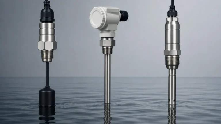
Flush Diaphragm Pressure Transducer
Flush Diaphragm Pressure Transducer
In industrial process control, the accuracy of level and pressure measurement is often challenged by the physical properties of the media being measured. Standard pressure sensors typically utilize a small orifice or a recessed sensing element that allows the process fluid to reach the internal diaphragm. While effective for clean liquids and gases, these designs are prone to failure when used with viscous, crystallizing, or solid-laden fluids. The flush diaphragm pressure transducer is engineered specifically to overcome these challenges by placing the sensing surface directly in contact with the process flow, eliminating the cavities where media can accumulate and harden.
For engineers and system integrators, selecting the correct sensing technology is critical for ensuring long-term reliability and reducing maintenance overhead. This guide examines the technical principles, selection criteria, and installation requirements for flush diaphragm pressure transducers within the context of modern industrial automation. To explore a wide range of industrial measurement instruments, technical professionals often refer to the Welk Main Page for detailed product specifications and application support.
Measurement Principles and Working Mechanisms
The fundamental operation of a flush diaphragm pressure transducer relies on the conversion of mechanical force into an electrical signal. Unlike standard sensors, the diaphragm is mounted "flush" with the process connection, meaning there is no internal dead space or "pressure port" leading to the sensor.
Hydrostatic Level Measurement
In many industrial applications, these transducers are used to measure the level of a liquid in a tank. This is based on the principle of hydrostatic pressure, where the pressure at the bottom of a vessel is directly proportional to the height of the liquid column above it. The relationship is defined by the formula:
P = ρ × g × h
Where:
* P is the hydrostatic pressure.
* ρ (rho) is the density of the liquid.
* g is the acceleration due to gravity (approximately 9.81 m/s²).
* h is the height of the liquid.
By measuring the pressure at the base of the tank, the transducer provides a signal that can be scaled to represent the liquid level in meters or millimeters.
Piezoresistive and Capacitive Sensing
The internal mechanism of the transducer typically employs one of two primary technologies:
1. Piezoresistive Sensors: These utilize a silicon or metal strain gauge bonded to the back of the diaphragm. When pressure deforms the diaphragm, the electrical resistance of the strain gauge changes. This change is processed by internal electronics to produce a standardized output signal, such as 4-20mA or 0-10V.
2. Capacitive Sensors: These measure the change in capacitance between the process diaphragm and a fixed internal electrode. Capacitive sensors are often preferred for low-pressure ranges due to their high sensitivity and robustness against overpressure events.
Why Use a Flush Diaphragm Design?
The primary advantage of the flush diaphragm pressure transducer is its ability to handle "difficult" media. In traditional sensors, a recessed diaphragm creates a small chamber where fluids can become trapped. This leads to several issues:
* Clogging and Blockage: In wastewater or paper pulp applications, solids can fill the pressure port, preventing the pressure from reaching the sensor and resulting in false readings.
* Crystallization: In chemical processing, some fluids solidify or crystallize when they cool or stagnate. If this occurs inside a sensor port, the transducer becomes inoperable.
* Bacterial Growth: In the food, beverage, and pharmaceutical industries, any dead space is a potential site for bacterial contamination. Flush diaphragms allow for effective Clean-in-Place (CIP) and Steam-in-Place (SIP) processes, as the entire sensing surface is exposed to the cleaning agents and high-velocity flow.
Key Evaluation Criteria for Selection
Selecting the right flush diaphragm pressure transducer requires a thorough understanding of the process environment. Engineers should evaluate the following factors before procurement.
1. Material Compatibility
The diaphragm is the primary wetted part and must resist chemical corrosion. Common materials include:
* 316L Stainless Steel: The standard for most water and food applications.
* Hastelloy C: Used for highly corrosive chemicals and aggressive acids.
* Tantalum: Reserved for the most extreme chemical environments where even Hastelloy may fail.
* Ceramic: Offers excellent abrasion resistance for slurries but may be more brittle than metal options.
2. Pressure Range and Overpressure Protection
It is essential to select a transducer with a range that matches the maximum expected pressure of the application. However, system spikes or "water hammer" can exceed the nominal range. Selecting a device with a high overpressure rating (often 2x to 5x the rated range) prevents permanent deformation of the diaphragm.
3. Temperature Limits
Process temperatures can significantly affect sensor accuracy. Flush diaphragm sensors are often exposed to high temperatures during CIP cycles (up to 140°C / 284°F). In such cases, a transducer with an integrated cooling element or a remote capillary seal may be necessary to protect the internal electronics.
4. Process Connections
Flush diaphragm transducers come with various mounting options:
* Threaded Connections (G1/2, G1): Common in general industrial hydraulics and water treatment.
* Tri-Clamp: The standard for hygienic applications in the dairy and pharmaceutical sectors.
* Flanged Connections: Used in heavy industrial tanks and chemical reactors where high pressure or large diameters are required.
Practical Selection Table
| Application Type | Media Characteristic | Recommended Diaphragm Material | Recommended Connection |
| :— | :— | :— | :— |
| Wastewater Treatment | High solids, sludge | 316L Stainless Steel | Threaded (Flush) |
| Food & Beverage | Viscous (Syrups, Dairy) | 316L / Electropolished | Tri-Clamp (Hygienic) |
| Chemical Processing | Aggressive Acids | Hastelloy C / Tantalum | Flange |
| Paper & Pulp | Fibrous Slurries | 316L / Hardened Coating | Large Diameter Flange |
| Pharmaceutical | High Purity, SIP required | 316L (Ra < 0.4 µm) | Tri-Clamp |
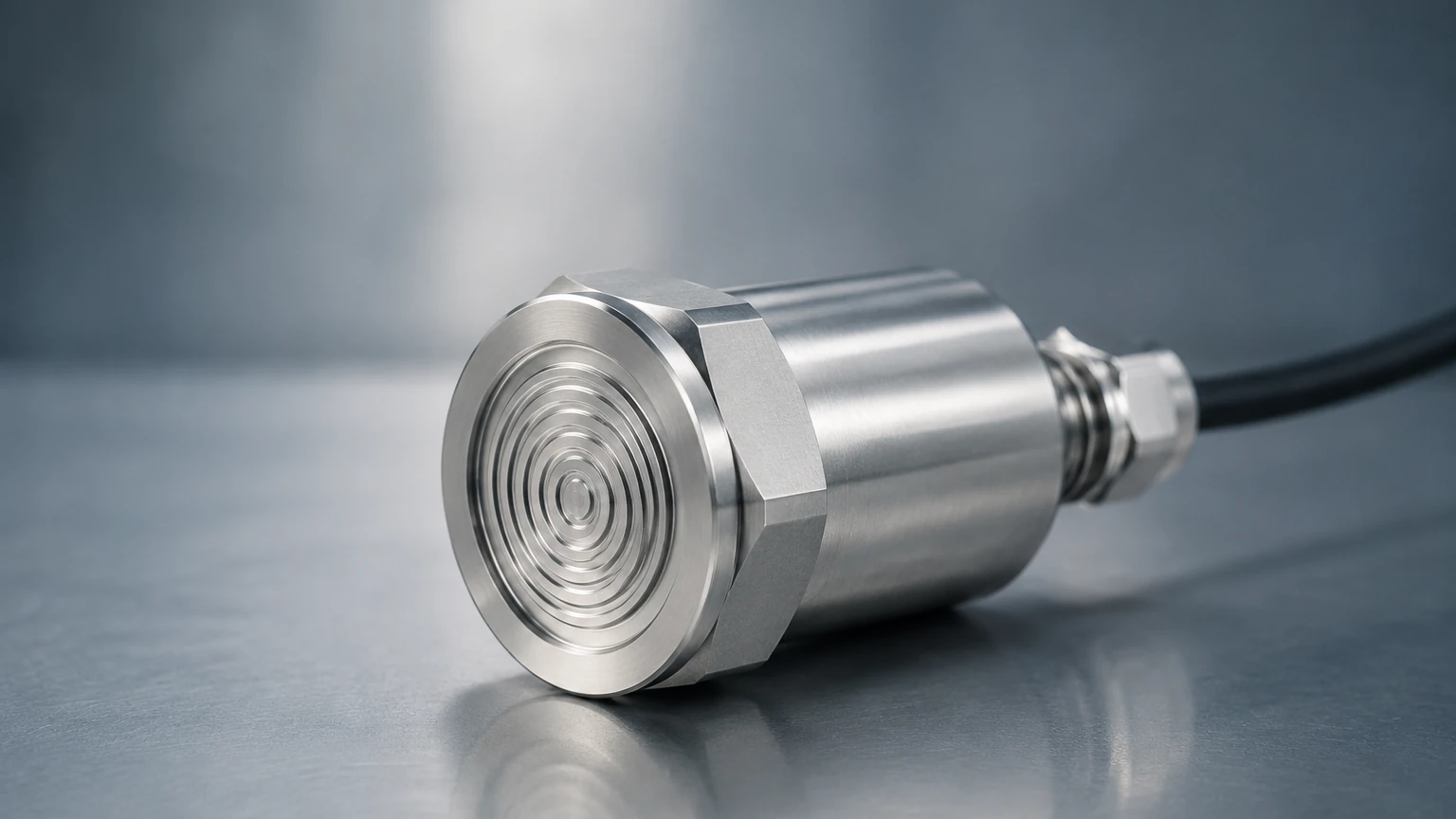
Installation Considerations and Best Practices
Proper installation is vital for the longevity and accuracy of a flush diaphragm pressure transducer. Because the diaphragm is exposed and relatively thin, it is susceptible to mechanical damage.
* Handle with Care: Never touch the diaphragm with fingers or tools. Even a small scratch or dent can alter the calibration or lead to premature fatigue failure.
* Orientation: For level measurement in tanks, the transducer should be installed at the lowest possible point to maximize the measurable range. In pipelines, avoid installing the sensor at the very bottom where sediment might settle, or at the very top where air pockets might form.
* Sealing and Torque: When installing threaded flush sensors, use the manufacturer-specified O-rings or gaskets. Over-tightening can stress the sensor housing and cause a zero-shift in the signal. Ensure the seal does not protrude into the flow path, as this creates a new area for material buildup.
* Venting: For gauge pressure sensors (measuring relative to atmospheric pressure), ensure the vent tube in the cable or housing is not blocked or exposed to moisture. Blocked vents will cause measurement errors as atmospheric pressure changes.
Limitations and Risks
While highly versatile, flush diaphragm pressure transducers are not a universal solution for every application. Engineers must be aware of the following limitations:
1. Fragility: The exposed diaphragm is more vulnerable to physical impact from large debris in a flow stream compared to recessed designs.
2. Temperature Sensitivity: Because the sensing element is closer to the process media, thermal expansion of the fill fluid (in oil-filled sensors) can cause "thermal drift." High-quality transducers include temperature compensation circuits to mitigate this effect.
3. Cost: Due to the specialized manufacturing and materials required for the flush face, these units are generally more expensive than standard pressure transmitters.
4. Abrasive Wear: In high-velocity slurry applications, the constant friction of particles against the diaphragm can thin the material over time, eventually leading to a rupture.
Frequently Asked Questions (FAQ)
Q: Can I use a flush diaphragm transducer for gas pressure measurement?
A: Yes, but it is rarely necessary unless the gas contains heavy condensates or contaminants that could clog a standard pressure port. For clean gas applications, a standard recessed sensor is usually more cost-effective.
Q: How often should these sensors be calibrated?
A: Calibration frequency depends on the criticality of the process and the severity of the environment. In stable water treatment applications, annual calibration is common. In high-temperature chemical processes, semi-annual checks may be required.
Q: What is the difference between a "flush" and a "semi-flush" diaphragm?
A: A true flush diaphragm sits perfectly level with the mounting surface. A semi-flush design may be slightly recessed (a few millimeters) to provide a degree of mechanical protection while still minimizing the volume where media can collect.
Q: Does the viscosity of the fluid affect the pressure reading?
A: No. Hydrostatic pressure is independent of viscosity. However, extremely high viscosity can slow the response time of the sensor if the media is so thick that it dampens the movement of the diaphragm.
Conclusion
The flush diaphragm pressure transducer is an essential tool for industrial automation, particularly in sectors dealing with non-clean fluids. By eliminating dead spaces and providing a robust, cleanable interface, these sensors ensure accurate level and pressure data in the most demanding environments. When selecting a device, engineers must balance material requirements, pressure ranges, and hygienic standards to achieve the best performance. For further technical guidance and to view a complete range of industrial level measurement solutions, visiting the Welk Main Page provides access to professional engineering resources and product documentation.