Flush Pressure Sensor
Flush Pressure Sensor
In industrial process control, the accuracy and reliability of pressure measurements are often challenged by the physical characteristics of the media being measured. Standard pressure transmitters typically utilize a small orifice or a recessed diaphragm to sense pressure. However, when dealing with viscous fluids, slurries, or media that crystallize, these standard designs are prone to clogging and failure. The flush pressure sensor is engineered specifically to overcome these challenges by placing the sensing diaphragm flush with the process connection, eliminating dead space where material can accumulate.
For engineers and system integrators, selecting the correct instrumentation is critical for maintaining uptime and ensuring process safety. Whether you are monitoring the level of a thick chemical pulp or ensuring the hygiene of a food processing line, understanding the mechanics and application boundaries of a flush pressure sensor is essential. For a broader look at the technology available for these environments, you can browse the Main Page of our technical catalog to compare various measurement solutions.
Measurement Principles of Flush Pressure Sensors
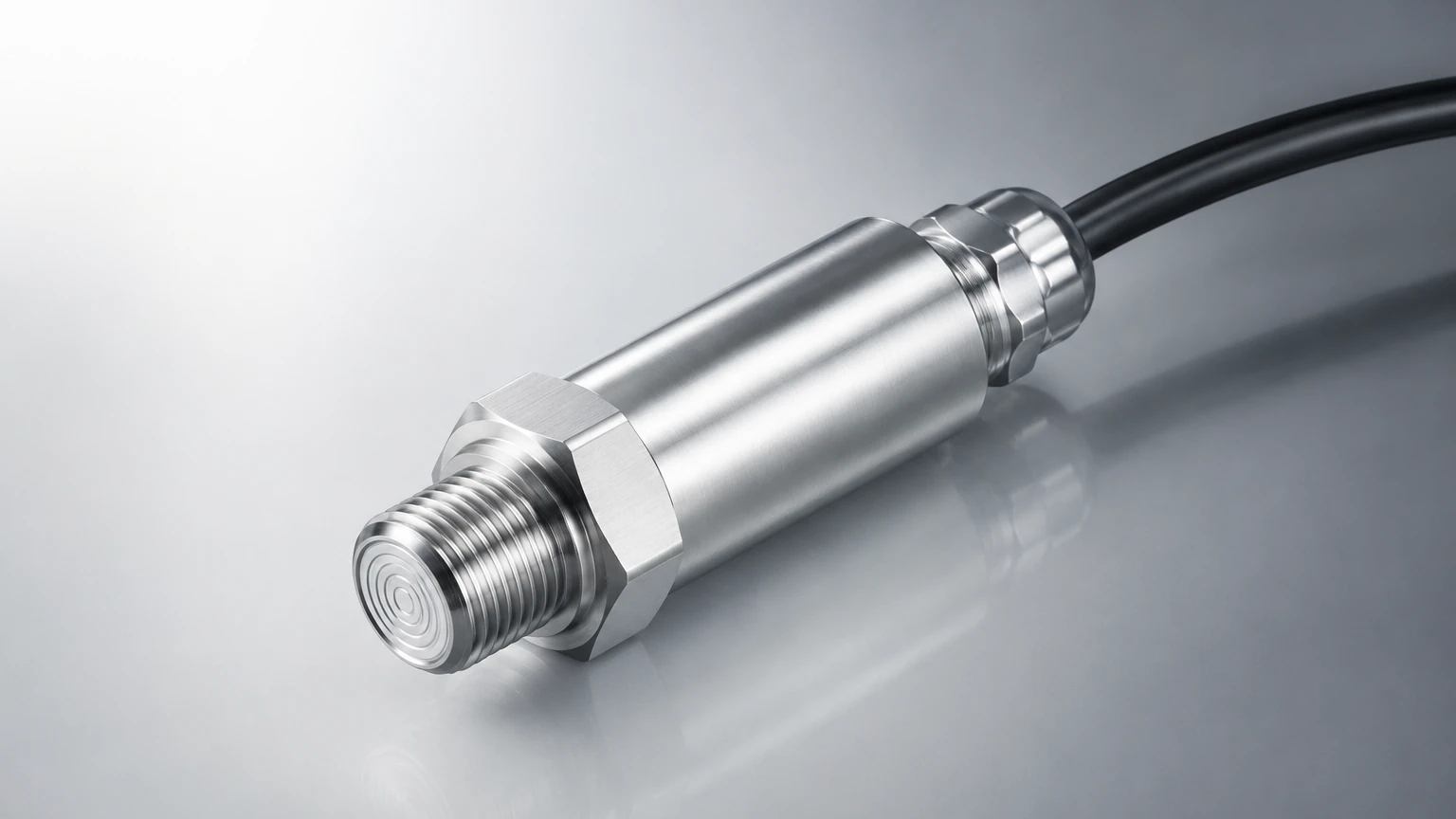
The fundamental principle of a flush pressure sensor is the conversion of mechanical force—exerted by a liquid or gas against a surface—into an electrical signal. Unlike standard sensors where the media must enter a small port to reach the diaphragm, the flush design presents a flat, smooth surface directly to the process media.
Hydrostatic Pressure and Force Transfer
Most flush pressure sensors used for level measurement operate on the principle of hydrostatic pressure. The pressure at the bottom of a tank is directly proportional to the height of the liquid column above it, calculated by the formula:
P = ρ · g · h
Where:
* P is the pressure (Pa or bar).
* ρ (rho) is the density of the fluid (kg/m³).
* g is the gravitational acceleration (approximately 9.81 m/s²).
* h is the height of the liquid (m).
When the process media presses against the flush diaphragm, the diaphragm undergoes a microscopic deflection. This deflection is transferred to a sensing element located behind the diaphragm. There are two primary technologies used for this conversion:
1. Piezoresistive Sensors: These utilize a silicon or metallic strain gauge bonded to the back of the diaphragm or a secondary internal sensor. As the diaphragm moves, the resistance of the gauge changes, which is then converted into a 4-20mA or digital signal.
2. Ceramic Capacitive Sensors: These involve a ceramic substrate and a moving ceramic diaphragm. The change in capacitance between the two plates as the diaphragm moves provides a highly stable and robust measurement, particularly in vacuum or high-overpressure conditions.
The Role of Internal Fill Fluids
In metallic flush pressure sensors, the space between the external flush diaphragm and the internal sensing chip is typically filled with a transmission fluid, such as silicone oil or vegetable oil (for food-grade applications). This fluid must be incompressible to ensure that the pressure exerted on the external face is transmitted accurately to the internal electronics without loss or lag.
Why Choose a Flush Diaphragm Design?
The primary advantage of the flush pressure sensor is its "clog-free" nature. In many industrial applications, the media is not a clean, free-flowing liquid.
Handling Viscous and Particulate Media
In industries such as wastewater treatment or pulp and paper, fluids often contain fibers, solids, or high viscosity (e.g., sludge or paper stock). A standard sensor with a pressure port would quickly become plugged, leading to "frozen" readings or complete sensor failure. The flush pressure sensor allows these materials to flow past the sensing face without getting trapped.
Hygienic Requirements
In the food, beverage, and pharmaceutical industries, hygiene is paramount. Any recessed area or "dead leg" in a piping system can harbor bacteria or allow old product to ferment. Flush sensors are designed to be compatible with Clean-in-Place (CIP) and Sterilize-in-Place (SIP) processes. The smooth surface ensures that cleaning agents can reach the entire wetted area of the sensor, maintaining the integrity of the production batch.
Crystallizing and Solidifying Media
Certain chemicals, such as liquid sulfur or concentrated brine, may crystallize or solidify if they cool down or remain stagnant in a small cavity. By using a flush pressure sensor, the sensing element remains in the main flow or tank volume, where temperature and movement are more consistent, reducing the risk of media solidification against the sensor face.
Technical Selection Criteria
Choosing the right flush pressure sensor requires a detailed analysis of the process conditions. Failure to account for chemical compatibility or temperature can lead to premature diaphragm fatigue or measurement drift.
Diaphragm Material Compatibility
The diaphragm is the most vulnerable part of the sensor. It must be thin enough to be sensitive but durable enough to withstand the process. Common materials include:
* 316L Stainless Steel: The standard for most water and food applications.
* Hastelloy C: Required for highly corrosive chemical environments involving acids or chlorides.
* Tantalum: Used for extremely aggressive media where even Hastelloy might fail.
* Ceramic (Al₂O₃): Offers excellent abrasion resistance for abrasive slurries.
Pressure Range and Overpressure
It is vital to select a sensor with a nominal range that matches your operating pressure while providing a sufficient safety margin. Overpressure events (such as water hammer) can permanently deform a thin flush diaphragm. Most high-quality sensors offer an overpressure rating of 2x to 5x the nominal range.
Temperature Considerations
Flush sensors are often mounted directly on tanks or pipes where temperatures can fluctuate. Because the internal fill fluid expands and contracts with temperature changes, this can cause a "zero shift" in the reading. For high-temperature applications (above 100°C), specialized cooling fins or capillary extensions may be necessary to protect the electronics.
Technical Selection Table
| Feature | Piezoresistive (Metallic) | Ceramic Capacitive |
| :— | :— | :— |
| Diaphragm Material | 316L, Hastelloy, Tantalum | 96% – 99.9% Alumina Ceramic |
| Accuracy | 0.1% to 0.5% FS | 0.1% to 0.2% FS |
| Overpressure Resistance | Moderate | Very High |
| Abrasion Resistance | Low (Thin metal) | High (Hard ceramic) |
| Vacuum Resistance | Limited | Excellent |
| Best Application | General purpose, high pressure | Abrasive slurries, vacuum tanks |
| Typical Units | 0-100 mbar to 0-400 bar | 0-40 mbar to 0-60 bar |
Installation and Maintenance Guidelines
Correct installation is the most critical factor in the longevity of a flush pressure sensor. Because the diaphragm is exposed and relatively thin (often 0.05mm to 0.1mm for metal versions), it can be easily damaged during handling.
Mounting Orientation and Sealing
Flush sensors are typically mounted via threaded connections (e.g., G1/2 or G1) or hygienic clamps (Tri-clamp).
* Avoid Diaphragm Contact: Never touch the diaphragm with fingers or tools. Even a small dent can change the calibration or cause the sensor to fail.
* Sealing: Ensure the O-ring or gasket is compatible with the process media. In flush designs, the seal is usually located just behind the diaphragm to ensure no gaps exist between the sensor and the mounting wall.
* Orientation: While these sensors can be mounted in any orientation, mounting them on the side or bottom of a tank is most common for level applications. If mounted on the bottom, ensure there is no heavy sediment buildup that could mechanically bury the sensor.
Calibration and Zeroing
After installation, it is standard practice to perform a zero-point adjustment. The weight of the internal fill fluid can cause a small offset depending on whether the sensor is mounted horizontally or vertically. Most modern transmitters allow for a "push-button" or HART-based zero trim to account for this mounting effect.
Common Risks and Mitigation Strategies
Despite their robust design, flush pressure sensors face specific risks in industrial environments.
1. Mechanical Damage: In processes with high-velocity flow or large solids, particles can strike the diaphragm. Mitigation: Use a ceramic diaphragm sensor, which is significantly harder and more scratch-resistant than stainless steel.
2. Hydrogen Permeation: In high-pressure applications involving hydrogen gas, hydrogen molecules can diffuse through a thin metal diaphragm, forming bubbles in the fill oil and causing massive signal drift. Mitigation: Specify gold-plated diaphragms to act as a barrier against hydrogen atoms.
3. Thermal Shock: Rapid changes in media temperature (e.g., during a CIP cycle where cold water follows hot steam) can cause the sensor signal to spike or drift. Mitigation: Select sensors with integrated temperature compensation or use a remote seal with a capillary to isolate the sensing element from the heat source.
Frequently Asked Questions (FAQ)
Q: Can a flush pressure sensor be used for vacuum measurement?
A: Yes, but caution is required. In metallic sensors, a deep vacuum can pull the diaphragm outward, potentially causing it to delaminate or leak. Ceramic capacitive sensors are generally superior for vacuum applications due to their rigid structure.
Q: How often should I calibrate my flush pressure sensor?
A: For critical processes, an annual calibration check is recommended. In stable, non-corrosive environments, the interval can often be extended to two or three years. Sensors in hygienic applications should be checked whenever the system is opened for major maintenance.
Q: What is the difference between a flush sensor and a remote seal?
A: A flush sensor has the diaphragm built directly into the process connection of the transmitter. A remote seal uses a capillary tube to connect the flush diaphragm to a transmitter located several meters away. Remote seals are used when the process temperature is too high for the transmitter electronics or when the transmitter needs to be mounted in a more accessible location.
Conclusion
The flush pressure sensor is an indispensable tool for challenging industrial environments where standard instrumentation would fail. By eliminating the recesses and ports that lead to clogging, these sensors provide a reliable, low-maintenance solution for measuring pressure and level in viscous, hygienic, or crystallizing media.
When selecting a sensor, engineers must balance material compatibility, pressure ranges, and the specific physical properties of the media. For detailed technical specifications and to explore the full range of level measurement technologies, including radar and ultrasonic alternatives, please visit our Main Page for professional guidance and product support.