Fmi51
Fmi51
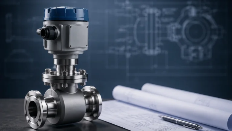
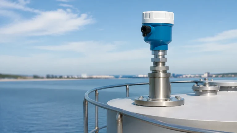
In the field of industrial process automation, continuous level measurement is a critical requirement for ensuring operational efficiency, safety, and inventory accuracy. The fmi51 is a prominent capacitive level probe designed for high-performance applications across various industries, including chemical processing, water treatment, and oil and gas. This rod probe is engineered to handle challenging conditions such as high pressures, extreme temperatures, and aggressive media.
Understanding the technical nuances of the fmi51 is essential for engineers and procurement professionals who need to select the most reliable instrumentation for their specific process requirements. This guide provides a comprehensive technical overview of the capacitance measurement principle, selection criteria, installation best practices, and the inherent limitations of this technology.
Understanding the Capacitance Measurement Principle
The fmi51 operates on the principle of capacitance. In simple terms, a capacitor consists of two conductive plates separated by an insulating material known as a dielectric. In a level measurement application, the probe itself acts as one plate of the capacitor, while the vessel wall (if metallic and grounded) acts as the second plate. The space between the probe and the wall is occupied by the process medium and the air or vapor space above it.
The Mathematical Foundation
The capacitance ($C$) of this system is determined by the formula:
$$C = \epsilon_0 \cdot \epsilon_r \cdot \frac{A}{d}$$
Where:
* $\epsilon_0$: The permittivity of free space (a constant).
* $\epsilon_r$: The relative dielectric constant of the material between the plates.
* $A$: The surface area of the plates.
* $d$: The distance between the plates.
In a vertical tank, the distance ($d$) and the surface area ($A$) of the probe remain constant. Therefore, the total capacitance is directly proportional to the dielectric constant ($\epsilon_r$) of the medium between the probe and the tank wall.
Conductive vs. Non-Conductive Media
The measurement behavior changes depending on the electrical properties of the liquid:
1. Non-Conductive Liquids (e.g., oils, hydrocarbons): The liquid acts as the dielectric. As the level rises, more of the probe is surrounded by the liquid (which has a higher $\epsilon_r$ than air), increasing the measured capacitance linearly with the level.
2. Conductive Liquids (e.g., water-based solutions, acids, alkalis): The liquid acts as an extension of the ground (the second plate). The insulation on the fmi51 probe (usually PFA or PTFE) becomes the dielectric. In this scenario, the capacitance is determined by the thickness of the probe insulation and the level of the liquid covering it. This results in a very high change in capacitance per unit of level, providing excellent resolution.
For more information on diverse measurement technologies and how they compare to capacitance, you may visit the Main Page of industrial instrumentation providers like Welk.
Key Features and Technical Specifications of the Fmi51
The fmi51 is designed as a robust rod probe for continuous level measurement. Its construction and electronics are optimized for stability and long-term reliability.
Construction and Materials
* Probe Rod: Typically constructed from high-grade stainless steel (316L).
* Insulation: To function in conductive liquids and to resist chemical attack, the rod is fully insulated with PFA (Perfluoroalkoxy) or PTFE (Polytetrafluoroethylene). This insulation is crucial for the capacitive principle and protects the probe from corrosion.
* Process Connections: Available in various threaded sizes (e.g., G 1/2", NPT 1/2") and flange standards (ANSI, DIN, JIS) to fit diverse vessel architectures.
Performance Limits
* Temperature Range: The fmi51 can typically operate in process temperatures ranging from -80°C to +200°C (-112°F to +392°F).
* Pressure Range: It is designed to withstand vacuum and high-pressure environments up to 100 bar (1450 psi), depending on the process connection and temperature.
* Measurement Range: Rod lengths can vary from 0.1 m to 4 m (approx. 4 inches to 13 feet). For taller tanks, cable-based versions of capacitive probes are generally preferred over the rigid rod of the fmi51.
Active Build-up Compensation
One of the significant advantages of the fmi51 electronics is the ability to compensate for "build-up" or coating. In many industrial processes, viscous or sticky media can leave a film on the probe after the level drops. Standard capacitance sensors might misinterpret this film as a high liquid level. The fmi51 utilizes advanced electronic algorithms to differentiate between the capacitance of a thin coating and the capacitance of the actual bulk liquid, ensuring accurate readings even in fouling services.
Application Suitability and Selection Criteria
Choosing the fmi51 requires an analysis of the process media and the vessel environment. While versatile, it is particularly effective in specific scenarios.
Ideal Applications
* Interface Measurement: The fmi51 is an excellent choice for detecting the interface between two liquids with different dielectric constants, such as oil and water.
* Small Vessels: Because it is a rod probe, it is ideal for small to medium-sized tanks where internal obstructions might interfere with non-contact methods like ultrasonic or radar.
* High-Pressure/High-Temperature Reactors: Its robust mechanical design allows it to function where sensitive electronic components of other technologies might fail.
Selection Table
| Factor | Requirement | Suitability for fmi51 |
| :— | :— | :— |
| Media State | Liquid | Excellent |
| Conductivity | High or Low | Excellent (requires insulation) |
| Vessel Material | Metal | Excellent (uses wall as ground) |
| Vessel Material | Plastic/Glass | Requires Ground Tube |
| Build-up/Coating | Moderate to Heavy | Good (with compensation) |
| Foam Surface | Present | Good (measures liquid level) |
| Agitation/Turbulence | Present | Good (mechanical stability) |
Installation Guidelines for Optimal Performance
Correct installation is paramount for the accuracy of any capacitive level sensor. Because the fmi51 relies on the electrical relationship between the probe and its surroundings, several physical factors must be considered.
1. Grounding and Reference
In a metallic tank, the vessel wall serves as the ground reference. It is vital that the process connection of the fmi51 has a low-resistance electrical contact with the tank. If the tank is lined with a non-conductive material or is made of plastic/GFRP, a ground tube (also known as a stilling well or bypass) must be used. The ground tube provides a fixed, known distance ($d$) for the capacitance calculation and ensures a stable reference.
2. Mounting Position
* Vertical Alignment: The probe should be mounted vertically. If mounted at an angle, the relationship between the level and the capacitance becomes non-linear and more difficult to calibrate.
* Distance from Walls: To prevent interference and ensure a linear measurement, the probe should be mounted at a consistent distance from the tank wall. A minimum distance of 50 mm (approx. 2 inches) is usually recommended.
* Inflow Proximity: Never install the probe directly in the path of the filling stream. The turbulence and the physical impact of the liquid can cause mechanical stress and erratic readings.
3. Inactive Length (Dead Zone)
At the top of the probe, near the process connection, there is an "inactive length." This is a section of the probe that does not contribute to the measurement. This design prevents the probe from shorting out against the nozzle or the tank roof. Engineers must account for this dead zone when calculating the maximum measurable level.

Limitations and Potential Risks
While the fmi51 is a highly capable instrument, users must be aware of its limitations to avoid measurement errors.
* Dielectric Constant Stability: Capacitance measurement assumes that the dielectric constant ($\epsilon_r$) of the medium is constant. If the composition of the liquid changes significantly (e.g., a chemical reaction that alters the $\epsilon_r$), the sensor will report an incorrect level unless it is recalibrated for the new medium.
* Heavy Bridging: While the fmi51 can handle thin coatings, "bridging"—where the medium creates a solid physical bridge between the probe and the tank wall—will cause the sensor to fail or read 100% level constantly.
* Moisture in the Housing: Like all electronic instruments, the housing must remain sealed. Moisture ingress into the electronics compartment can change the internal capacitance and lead to significant drift or total failure.
* Vapor Phase Variations: In high-pressure gas applications, the dielectric constant of the vapor space can change with pressure and temperature. While usually negligible at atmospheric pressure, this can introduce errors in high-pressure steam or gas applications.
Maintenance and Troubleshooting
The fmi51 is a low-maintenance device due to its lack of moving parts. However, periodic checks are recommended to ensure long-term accuracy.
1. Visual Inspection: Periodically check the probe insulation for signs of wear, pitting, or chemical degradation. Any breach in the PFA/PTFE coating in a conductive liquid will result in a short circuit and measurement failure.
2. Calibration Verification: Verify the 4 mA (empty) and 20 mA (full) points. This is best done by physically changing the level in the tank, though some modern electronics allow for simulation and dry calibration based on known dielectric constants.
3. Build-up Check: If the level reading becomes sluggish or fails to return to zero when the tank is empty, inspect the probe for excessive build-up that may exceed the compensation limits of the electronics.
Frequently Asked Questions (FAQs)
Q: Can the fmi51 be used for solids or powders?
A: No, the fmi51 is specifically designed for liquids. For bulk solids, different probe geometries and higher-tensile-strength cable probes are required to withstand the lateral forces of the material.
Q: Is calibration required upon installation?
A: Yes. Because capacitance depends on the specific geometry of the tank and the dielectric properties of the medium, a "Full" and "Empty" calibration is necessary to map the measured capacitance to the 4-20mA output.
Q: What happens if the probe insulation is damaged?
A: If the insulation is damaged and the liquid is conductive, the probe will short to the liquid, typically resulting in an error signal or a constant "maximum" level reading. In non-conductive liquids, the probe might continue to function but with reduced accuracy and a high risk of corrosion to the stainless steel rod.
Conclusion
The fmi51 remains a staple in industrial level measurement due to its mechanical simplicity and ability to withstand harsh process conditions. By understanding the underlying capacitive principle and adhering to strict installation guidelines, operators can achieve high-precision level monitoring. For applications where capacitance might not be the optimal fit—such as those with frequently changing media compositions—alternative technologies like radar or ultrasonic sensors should be evaluated. To explore a wide range of industrial level measurement solutions and technical support, professionals are encouraged to consult the Main Page of specialized manufacturers like Welk.