Fmr50
Fmr50
In the landscape of industrial process automation, the FMR50 represents a standard-setting technology for non-contact radar level measurement. Primarily utilized for liquid level monitoring in storage tanks, buffer vessels, and utility processes, this instrument utilizes microwave pulses to determine the distance to a product surface. For engineers and procurement specialists, understanding the technical nuances of the FMR50—and how it compares to broader industrial level measurement solutions—is essential for ensuring process safety, accuracy, and long-term reliability.
As a professional manufacturer of industrial level measurement instruments, Welk provides a comprehensive range of radar, ultrasonic, and hydrostatic solutions. By examining the operational principles of the FMR50, we can better appreciate the engineering requirements of modern industrial automation. For those seeking specific product options or technical support for level measurement projects, visiting the Main Page of a specialized manufacturer offers a direct route to tailored instrumentation solutions.
Measurement Principles of Radar Level Technology
To understand the FMR50, one must first understand the fundamental physics of Time-of-Flight (ToF) radar measurement. The device operates on a non-contact principle, which is inherently advantageous in applications involving corrosive, viscous, or abrasive media.
The Pulse Radar Method
High-frequency radar pulses (typically in the 26 GHz C-band or K-band range) are emitted by the antenna. These pulses travel at the speed of light, reach the surface of the medium, and are reflected back to the sensor. The electronics within the transmitter measure the time elapsed between the emission of the pulse and its reception.
Since the speed of light is constant, the distance ($D$) to the surface is calculated using the formula:
$D = c \times \frac{t}{2}$
where $c$ is the speed of light and $t$ is the measured time. The level ($L$) in the tank is then derived by subtracting the distance ($D$) from the total tank height ($E$): $L = E – D$.
Signal Processing and Echo Mapping
One of the critical features of the FMR50 and similar high-end radar meters is the ability to filter out "false echoes." In an industrial tank, internal structures such as agitators, heating coils, or ladders can reflect radar signals. Advanced software algorithms perform echo mapping, allowing the device to "learn" the static environment of the tank and ignore reflections from fixed obstructions, focusing only on the dynamic signal from the liquid surface.
Technical Specifications and Capabilities
The FMR50 is engineered for standard applications where extreme temperatures or pressures are not the primary concern, but where precision is required.
* Measuring Range: Typically up to 35 meters (approximately 115 feet) for liquids, though this depends heavily on the dielectric constant of the medium.
* Accuracy: Standard accuracy is often within ±2 mm, providing the high resolution needed for inventory control.
* Frequency: Operating at approximately 26 GHz, the device offers a focused beam angle, which is smaller than lower-frequency 6 GHz radars, allowing for easier installation in narrow nozzles.
* Process Temperature: Generally rated for environments between -40°C and +130°C.
* Process Pressure: Designed to operate from vacuum up to 3 bar (43.5 psi).
Comparison of Level Measurement Technologies
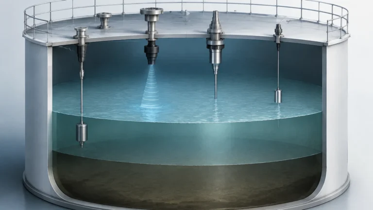
Selecting the right instrument requires a comparison of the FMR50’s radar technology against other common methods like ultrasonic or hydrostatic measurement. The following table provides a practical selection reference for engineering teams.
| Feature | Radar (FMR50) | Ultrasonic Sensors | Hydrostatic Transmitters |
| :— | :— | :— | :— |
| Measurement Type | Non-contact (Microwave) | Non-contact (Sound) | Contact (Pressure) |
| Accuracy | Very High (±2 mm) | Moderate (±0.2% of range) | High (±0.1% to 0.2%) |
| Vapor Sensitivity | Unaffected | Highly Sensitive | Unaffected |
| Vacuum Suitability | Excellent | Poor | Excellent |
| Installation | Top-mounted | Top-mounted | Side or Bottom-mounted |
| Cost | Higher | Lower | Moderate |
| Best Use Case | Process tanks with vapor/dust | Open channels/Water pits | Deep wells/Vented tanks |
Application Suitability
The FMR50 is a versatile tool, but its performance is optimized for specific industrial scenarios:
1. Water and Wastewater Treatment: Monitoring levels in chemical storage tanks (e.g., flocculants or acids) where non-contact measurement prevents sensor corrosion.
2. Food and Beverage: Use in buffer tanks where hygiene is paramount. The non-contact nature ensures no risk of contamination from the sensor itself.
3. Chemical Processing: Ideal for storage of solvents or base chemicals that do not exceed the pressure and temperature limits of the device.
4. Utility Storage: Monitoring diesel fuel or lubrication oil levels in power generation or manufacturing facilities.
Installation Considerations
Proper installation is the single most important factor in the performance of an FMR50 radar meter. Even the most advanced sensor will fail if the physical mounting ignores the laws of physics.
Nozzle Geometry
The radar antenna should ideally extend beyond the bottom of the mounting nozzle. If the nozzle is too long or narrow, it can create internal reflections that interfere with the near-range measurement. For an FMR50 with a standard horn antenna, the nozzle height should be kept as short as possible.
Beam Path and Obstructions
The radar signal spreads in a cone shape. The "beam angle" (often around 10° to 20° depending on the antenna size) must be kept clear of obstructions.
* Avoid the Center: Do not mount the sensor in the exact center of a domed tank, as this can cause multiple reflections to converge, confusing the sensor.
* Avoid the Wall: Maintain a minimum distance from the tank wall (typically 1/6th of the tank diameter) to prevent signal interference from the wall surface.
* Inflow Interference: Never install the sensor directly above the filling stream. The turbulence and the falling liquid will cause signal scatter and inaccurate readings.
Alignment
The antenna must be aligned perpendicular to the liquid surface. In tanks with agitated surfaces, a slight tilt or the use of a stilling well may be necessary to ensure a consistent return signal.

Limitations and Constraints
While the FMR50 is highly capable, it is not a universal solution. Engineers must be aware of the following limitations:
* Dielectric Constant (DC): Radar depends on the reflectivity of the medium. Liquids with a very low dielectric constant (e.g., liquid gases or some hydrocarbons) reflect very little energy. If the DC is below 1.6, a stilling well or a different technology (like guided wave radar) might be required.
* Heavy Foam: Dense, thick foam can absorb radar signals rather than reflecting them. While light foam is often penetrable, heavy protein-based foams can lead to signal loss.
* Extreme Pressure/Temperature: For high-pressure boilers or high-temperature reactors exceeding 130°C, specialized radar models with ceramic seals and cooling fins are required.
Maintenance and Troubleshooting
Radar meters are generally low-maintenance because they have no moving parts. However, periodic checks are recommended:
1. Antenna Buildup: In applications with splashing or condensation, material may build up on the antenna. While many modern radars can compensate for some buildup, heavy coating will eventually attenuate the signal.
2. Signal Quality (SNR): Use the device’s diagnostic interface to check the Signal-to-Noise Ratio. A degrading SNR often indicates that the antenna needs cleaning or that the process conditions have changed (e.g., increased turbulence).
3. Cable Glands: Ensure that cable entries are sealed and that a drip loop is used to prevent moisture from entering the electronics housing.
Frequently Asked Questions (FAQ)
Q: Can the FMR50 measure the level of solids?
A: The FMR50 is optimized for liquids. For bulk solids, a radar with a higher frequency (like 80 GHz) or a specialized solids-handling antenna is usually preferred due to the steep angle of repose and the dusty environment.
Q: Does the FMR50 work in a vacuum?
A: Yes. Unlike ultrasonic sensors, which require air to transmit sound waves, radar waves travel through a vacuum without any loss of accuracy.
Q: How do I handle measurement in a tank with an agitator?
A: You can use the "False Echo Suppression" feature to map out the agitator blades. It is best to perform this mapping while the agitator is moving if possible, or use a stilling well to isolate the liquid surface from the turbulence.
Conclusion
The FMR50 serves as a reliable workhorse for liquid level measurement across various industries. By leveraging the 26 GHz pulse radar principle, it provides a balance of precision, range, and ease of installation. However, the success of any level measurement project depends on matching the specific process conditions—such as the dielectric constant, temperature, and tank geometry—to the right instrument.
For engineers looking to implement robust level measurement systems, exploring the full catalog of industrial sensors is a critical step. Manufacturers like Welk provide the technical expertise and customized OEM/ODM services necessary to solve complex automation challenges. To review the latest in radar, ultrasonic, and hydrostatic technology, please refer to the Main Page for detailed product specifications and application support.