Frac Tank Level Monitoring
Frac Tank Level Monitoring
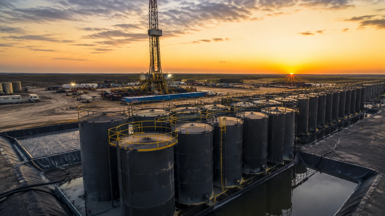
In industrial fluid management, frac tanks serve as essential mobile storage units for water, chemicals, and hydrocarbons. Effective frac tank level monitoring is critical for maintaining operational continuity, ensuring environmental safety, and optimizing logistics. Whether used in hydraulic fracturing, large-scale water treatment, or temporary chemical storage, these tanks require robust instrumentation to prevent overfills and manage inventory across remote sites.
Selecting the appropriate level measurement technology involves understanding the physical properties of the stored media, the environmental conditions of the site, and the specific mechanical constraints of the frac tank itself. This guide provides a technical overview of measurement principles, selection criteria, and installation best practices for engineering and operations teams.
Core Measurement Principles for Frac Tanks
Before selecting a specific instrument, it is necessary to understand the underlying physical principles used to detect fluid levels. Each technology interacts differently with the liquid surface and the internal tank environment.
Non-Contact Radar (Microwave)
Non-contact radar level meters emit high-frequency microwave pulses (typically in the 26 GHz or 80 GHz range). These pulses travel to the liquid surface, reflect back, and the sensor calculates the distance based on the "Time of Flight" (ToF).
* Advantages: Radar is unaffected by air temperature, pressure, or the presence of vapors. It is highly accurate and does not require contact with the fluid, reducing maintenance needs.
* Limitations: The dielectric constant (DK) of the liquid must be high enough to reflect the signal. Very low DK fluids may require specialized high-sensitivity radar units.
Ultrasonic Level Sensors
Ultrasonic sensors function similarly to radar but use sound waves instead of microwaves. The sensor emits a sound pulse that bounces off the liquid surface. The time taken for the echo to return determines the level.
* Advantages: This is a cost-effective solution for many water-based applications.
* Limitations: Sound speed is affected by air temperature and density. Ultrasonic signals can also be absorbed by heavy foam or distorted by significant vapor layers and wind in open-top tanks.
Hydrostatic Pressure Transmitters
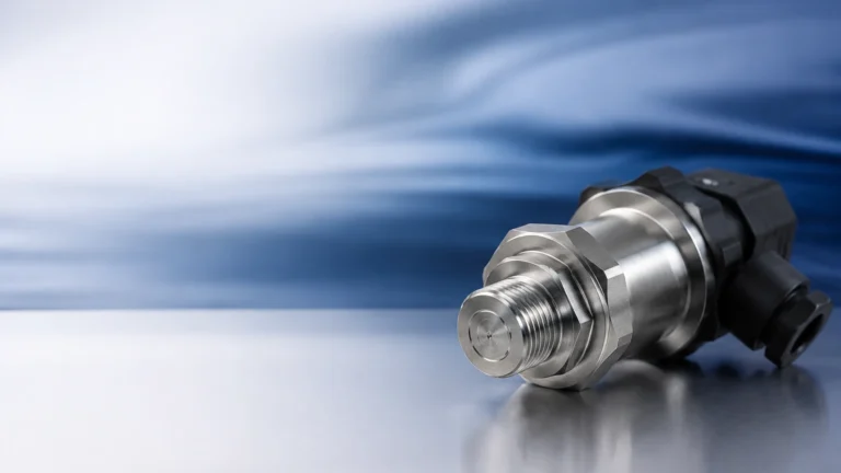
Hydrostatic monitoring measures the pressure exerted by the liquid column at the bottom of the tank. The pressure is proportional to the height of the liquid and its density ($P = \rho gh$).
* Advantages: Simple to install via a bottom-mounted port or as a submersible probe. It provides a direct measurement of the liquid's weight.
* Limitations: If the density of the fluid changes (e.g., switching from fresh water to heavy brine), the sensor must be recalibrated to maintain accuracy.
Guided Wave Radar (GWR)
Guided wave radar uses a probe or cable that extends into the liquid. The microwave pulse travels along the probe, reflects off the surface, and returns to the transmitter.
* Advantages: GWR is highly effective for fluids with low dielectric constants and is less affected by internal tank obstructions or turbulence.
* Limitations: Because it is a contact-based technology, the probe is susceptible to coating or physical damage if the tank contains heavy solids or agitators.
Key Evaluation Criteria for Frac Tank Applications
When evaluating systems for frac tank level monitoring, engineers must look beyond basic accuracy. The mobile and often harsh nature of frac tank operations introduces several variables.
1. Media Compatibility
Frac tanks often store "slickwater," which contains friction reducers, or produced water containing salts, oils, and residual chemicals. The chosen sensor must be chemically compatible with these substances. For acidic or corrosive fluids, PVDF or PTFE-coated sensors are preferred over standard stainless steel.
2. Physical Tank Geometry
Standard frac tanks are typically 12 to 15 meters (approx. 40 to 50 feet) long and roughly 2.5 to 3 meters (8 to 10 feet) high. However, internal structures like suction lines, heating coils, or ladders can interfere with radar or ultrasonic signals. Selecting a sensor with a narrow beam angle (such as 80 GHz radar) helps avoid these false reflections.
3. Power and Connectivity
Many frac tanks are deployed in remote areas without access to grid power. Monitoring systems must often operate on battery or solar power. Furthermore, the data must be transmitted to a central dashboard. Integration with cellular (LTE-M/NB-IoT) or satellite telemetry is a standard requirement for modern frac tank level monitoring.
Technology Selection Table
| Technology | Typical Accuracy | Media Suitability | Best Use Case |
| :— | :— | :— | :— |
| Non-Contact Radar | ±2 mm | Chemicals, Hydrocarbons, Water | High-precision, vapor-heavy environments |
| Ultrasonic | ±0.25% of range | Clean Water, Dilute Liquids | Cost-sensitive water storage |
| Hydrostatic | ±0.1% to 0.5% | Heavy sludges, Brines | Tanks with limited top access |
| Guided Wave Radar | ±3 mm | Low DK fluids, Foam | Small tanks with internal obstructions |
Installation and Calibration Considerations
Proper installation is as critical as selecting the right sensor. For frac tanks, which are frequently moved and refilled, the installation must be rugged.
Mounting Position
The sensor should be mounted away from the tank walls to prevent signal interference. For radar and ultrasonic sensors, the "dead zone" or "blocking distance" must be accounted for; the sensor should be high enough that the maximum liquid level never enters this zone (typically 100 mm to 300 mm depending on the model).
Dealing with Foam and Agitation
If the frac tank uses an internal manifold or if the filling process creates significant foam, ultrasonic sensors may fail to provide a reading. In these instances, non-contact radar or hydrostatic sensors are more reliable. If the tank is agitated, a stilling well can be used to provide a calm surface for the measurement.
Environmental Protection
Since frac tanks are used outdoors, sensors must have a high Ingress Protection (IP) rating, typically IP67 or IP68. In oil and gas applications, the equipment must also meet hazardous area certifications (ATEX/IECEx or Class I, Div 1) to ensure safety near flammable vapors.
Common Risks and Limitations
While modern instrumentation is highly reliable, certain risks can compromise the accuracy of frac tank level monitoring:
* Sensor Fouling: In tanks containing paraffin, heavy oils, or biological growth, material can build up on the sensor face or probe. Regular inspection cycles are necessary for contact-based sensors.
* Signal Loss in Vapors: While radar penetrates most vapors, extremely dense steam or chemical vapors can occasionally attenuate signals. Choosing the correct frequency (e.g., 80 GHz) mitigates this risk.
* Mechanical Damage during Transport: Frac tanks are subject to significant vibration and impact during mobilization. Sensors should be either removed during transport or mounted in protected, recessed housings.
Frequently Asked Questions (FAQ)
Q: How often do frac tank level sensors need calibration?
A: For non-contact radar, calibration is usually performed at commissioning and rarely needs adjustment unless the tank geometry changes. Hydrostatic sensors may need recalibration if the fluid density changes significantly.
Q: Can one sensor type work for all frac tank fluids?
A: While 80 GHz non-contact radar is the most versatile, it may not be the most cost-effective for simple fresh-water storage where ultrasonic or hydrostatic sensors would suffice.
Q: How do I monitor multiple frac tanks on one site?
A: Most modern systems use a wireless gateway. Each tank is fitted with a sensor and a local radio/cellular node, which transmits data to a single cloud-based platform for fleet-wide visibility.
Q: What is the impact of temperature on measurement?
A: Ultrasonic sensors are highly sensitive to temperature changes because the speed of sound varies with air density. Radar is virtually unaffected by temperature fluctuations, making it superior for extreme climates.
Conclusion and Technical Confirmation
Implementing a reliable monitoring solution requires a thorough audit of the operational environment. Before proceeding with a hardware purchase, project managers should confirm the following:
1. Chemical Composition: Ensure the wetted parts of the sensor (stainless steel, Hastelloy, or plastics) are compatible with the fluid and any additives.
2. Mounting Options: Verify if the tank has existing 2-inch or 4-inch NPT/flanged ports available for sensor installation.
3. Data Integration: Determine if the level data needs to integrate into an existing SCADA system or a standalone mobile application.
By matching the measurement principle to the specific challenges of the site, operators can reduce the risk of environmental incidents and improve the efficiency of fluid logistics. For a comprehensive review of available instrumentation and technical specifications for industrial applications, visit the Main Page to explore specific product configurations and engineering support.