Flow Line Pipe
Flow Line Pipe
In industrial fluid handling, a flow line pipe serves as the critical link between the source of production—such as an oil wellhead or a chemical reactor—and the initial processing equipment, manifolds, or storage facilities. These pipelines are designed to transport complex mixtures of liquids, gases, and solids under varying pressures and temperatures. For engineers and facility managers, understanding the interplay between the physical characteristics of the flow line pipe and the instrumentation required to monitor its contents is essential for operational safety and efficiency.
Reliable monitoring of these systems often involves precise level measurement within the vessels the pipes feed into, or within the pipes themselves in the case of partially filled lines. To explore a comprehensive range of industrial instrumentation, you can visit the Main Page for detailed product specifications and application support.
Understanding Flow Line Pipe in Industrial Systems
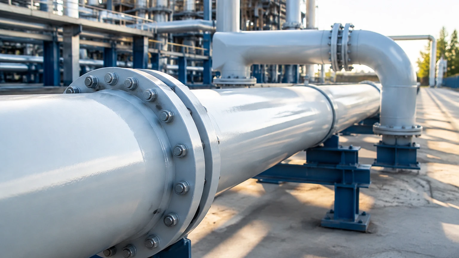
A flow line pipe is distinct from a transmission pipeline. While transmission lines move refined or processed products over long distances, flow lines are typically shorter and found within the boundaries of a production field or industrial plant. They are the first stage of transport for "raw" fluids, which may contain corrosive elements, abrasive sands, or multi-phase mixtures (oil, water, and gas).
Material and Construction Standards
In the oil and gas sector, flow line pipes are commonly manufactured according to API 5L specifications. Common materials include:
- Carbon Steel: The industry standard for non-corrosive service, often used for its cost-effectiveness and strength.
- Stainless Steel (304/316): Utilized in chemical processing or where the fluid contains corrosive agents like CO2 or H2S.
- Duplex Stainless Steel: Reserved for high-pressure, highly corrosive environments where both strength and corrosion resistance are paramount.
- Reinforced Thermoplastics (RTP): Increasingly used for smaller diameter lines to eliminate corrosion risks entirely.
Pipe diameters typically range from 50 mm (2 inches) to 300 mm (12 inches), depending on the flow volume and the required velocity to prevent solids from settling.
The Role of Level Measurement in Flow Line Management
Flow lines do not operate in isolation. They terminate in separators, slug catchers, or storage tanks where the separation of gas and liquid occurs. Accurate level measurement at these termination points is vital for several reasons:
1. Separator Efficiency: Maintaining the correct interface between oil and water ensures that the output meets quality specifications.
2. Pump Protection: Level switches prevent pumps from running dry or cavitating, which can lead to catastrophic mechanical failure.
3. Overfill Prevention: High-level alarms are critical for environmental safety, preventing spills from storage tanks fed by flow lines.
4. Slug Management: In multi-phase flow, large "slugs" of liquid can overwhelm downstream equipment. Level sensors in slug catchers provide the data needed to modulate flow rates.
Measurement Principles for Flow Line Applications
Before selecting instrumentation for a system involving a flow line pipe, it is necessary to understand the underlying measurement principles. Each technology has specific strengths depending on the fluid properties and environmental conditions.
1. Radar Level Measurement (ToF)
Radar sensors, both non-contact and guided wave (GWR), operate on the Time-of-Flight (ToF) principle. The sensor emits a high-frequency electromagnetic pulse that travels to the liquid surface and reflects back.
- Non-contact Radar: Ideal for corrosive or volatile liquids as the sensor does not touch the medium. It is unaffected by changes in density or pressure.
- Guided Wave Radar: Uses a probe to guide the signal. This is particularly effective for low dielectric liquids or when there is heavy turbulence at the flow line outlet.
2. Ultrasonic Level Measurement
Ultrasonic sensors emit sound waves at frequencies above the human hearing range. The time taken for the echo to return is proportional to the distance. While cost-effective, ultrasonic measurement is sensitive to air temperature variations and cannot be used in vacuums or high-pressure environments (typically limited to 3 bar / 43.5 psi).
3. Hydrostatic Level Measurement
This principle relies on the relationship between the height of a liquid column and the pressure it exerts at the base: $P = \rho \cdot g \cdot h$. By measuring the pressure, the level can be calculated if the density ($\rho$) is known. This is a robust method for vented tanks but requires compensation if the tank is pressurized.
4. Magnetic Level Gauges
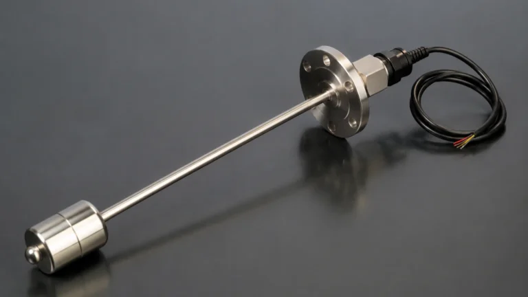
Used primarily for visual confirmation and high-pressure applications, these devices use a float containing a magnet that moves with the liquid level inside a bypass chamber connected to the flow line or vessel. The magnet flips external flags or interacts with a reed chain for electronic output.
Technical Selection Criteria
Choosing the right instrumentation for a flow line pipe system requires a systematic evaluation of the process parameters. The following table provides a general guide for technology selection based on common industrial requirements.
Table 1: Level Sensor Selection Guide
| Criteria | Non-Contact Radar | Guided Wave Radar | Ultrasonic | Hydrostatic | Magnetic Gauge |
| :— | :— | :— | :— | :— | :— |
| Accuracy | High (±2mm) | High (±2mm) | Moderate (±0.25%) | Moderate | Moderate |
| Max Pressure | Up to 160 bar | Up to 400 bar | < 3 bar | Depends on sensor | Up to 250 bar |
| Max Temp | Up to 450°C | Up to 450°C | < 80°C | < 100°C | Up to 400°C |
| Foam Impact | Moderate | Low | High | None | None |
| Installation | Top-mounted | Top-mounted | Top-mounted | Bottom/Side | Side-mounted |
| Cost | High | Moderate/High | Low | Moderate | Moderate |
Installation and Engineering Best Practices
Proper installation of both the flow line pipe and its associated sensors is critical to prevent measurement errors and mechanical wear.
Pipe Slope and Drainage
Flow lines should be installed with a slight slope (typically 1:100) to ensure proper drainage during shutdowns and to prevent the accumulation of liquids in gas lines (condensate) or gases in liquid lines (gas pockets). If the pipe feeds into a level-controlled vessel, the entry point should be designed to minimize turbulence.
Sensor Placement
- Avoid Inlets: Never install a level sensor directly above the point where the flow line pipe enters a tank. The turbulence and splashing will result in erratic readings.
- Stilling Wells: For high-velocity flow or agitated liquids, installing the sensor inside a stilling well (a perforated pipe) can stabilize the surface and improve accuracy.
- Dead Zones: Be aware of the "dead zone" or "blocking distance" at the top of ultrasonic and radar sensors. If the liquid level enters this zone, the sensor will fail to provide a reading.
Dealing with Turbulence
In systems where the flow line pipe delivers fluid at high velocity, surface ripples can scatter radar or ultrasonic signals. In such cases, Guided Wave Radar (GWR) is often the preferred choice because the probe acts as a waveguide, ensuring the signal reaches the surface and returns regardless of surface conditions.
Common Challenges and Limitations
Engineers must account for several physical phenomena that can interfere with flow line pipe operations and monitoring:
1. Paraffin and Scale Buildup: In oil production, waxes (paraffins) can coat the interior of the pipe and the surface of level probes. This requires regular pigging of the pipes and the selection of non-contact sensors or probes with specialized coatings.
2. Multi-phase Flow: When a flow line carries a mix of gas and liquid, standard flow meters may fail. Level sensors in a separator are then used as a proxy to calculate flow rates via "tank gauging" or "dump counting."
3. Ambient Temperature Fluctuations: In outdoor installations, extreme cold can increase fluid viscosity, while extreme heat can affect sensor electronics. Insulation or heat tracing for the flow line pipe may be necessary.
4. Dielectric Constant (Dk): For radar measurement, the liquid must have a high enough dielectric constant to reflect the signal. Hydrocarbons have low Dk values, requiring more sensitive radar units or GWR.
Frequently Asked Questions (FAQs)
Q: What is the difference between a flow line and a gathering line?
A: A flow line pipe typically connects a single wellhead to a separator or manifold. A gathering line collects fluids from multiple flow lines and transports them to a central processing facility.
Q: Can I use ultrasonic sensors for high-pressure flow lines?
A: Generally, no. Ultrasonic waves require a medium (air or gas) to travel. At high pressures, the density of the gas changes, significantly affecting the speed of sound and measurement accuracy. Furthermore, the transducer face may not be rated for high pressure. Radar is the better alternative.
Q: How do I prevent corrosion in a steel flow line pipe?
A: Common methods include the injection of chemical corrosion inhibitors, internal plastic coatings, or using cathodic protection. For highly aggressive media, upgrading to stainless steel or composite piping is recommended.
Q: Why is hydrostatic level measurement popular in water treatment flow lines?
A: It is highly reliable, relatively inexpensive, and easy to maintain. Since water density is constant and the tanks are usually vented to the atmosphere, the pressure-to-level conversion is very accurate.
Q: How often should level sensors on flow lines be calibrated?
A: This depends on the criticality of the process. For safety-instrumented systems (SIS), annual proof testing is common. For standard process monitoring, a bi-annual check against a manual dip tape or a sight glass is usually sufficient.
By integrating robust flow line pipe design with the appropriate level measurement technology, industrial operators can ensure long-term reliability and minimize the risk of costly downtime or environmental incidents. For further technical details on selecting the right instrument for your specific application, refer to the Main Page for expert guidance.