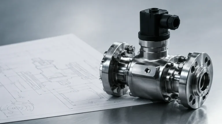
Fuel Tank Level Sensors
Fuel Tank Level Sensors
In industrial environments, the accurate measurement of fuel levels is a critical requirement for operational efficiency, safety, and environmental compliance. Whether managing bulk storage for diesel generators, monitoring aviation fuel in refineries, or tracking fuel consumption in heavy machinery, the choice of fuel tank level sensors directly impacts the reliability of the data collected. This guide examines the underlying physics of common measurement technologies, provides selection criteria for various fuel types, and outlines the practical engineering considerations necessary for successful deployment.
Understanding Fuel Tank Level Measurement Principles
Before selecting a sensor, it is essential to understand the physical principles that govern how different instruments detect the surface of a liquid fuel. Fuel, typically a hydrocarbon, presents specific challenges such as vapor generation, temperature-dependent density changes, and varying dielectric constants.
Hydrostatic Pressure Measurement
Hydrostatic level sensors operate on the principle that the pressure at the bottom of a tank is directly proportional to the height of the liquid column above it. The relationship is defined by the formula: $P = \rho \times g \times h$, where $P$ is pressure, $\rho$ (rho) is the density of the fuel, $g$ is the gravitational constant, and $h$ is the height of the liquid.
In practical applications, a submersible pressure transmitter is lowered to the bottom of the tank or mounted to a flange at the base. These sensors are highly effective for vented (atmospheric) tanks. However, because they measure weight, any change in the fuel's temperature that affects its density will introduce a measurement error unless compensated for by the control system. For example, diesel fuel expands as temperature rises, decreasing its density; a hydrostatic sensor might report a lower level than actually exists if density is assumed to be constant.
Ultrasonic (Time-of-Flight)
Ultrasonic sensors are non-contact devices that emit high-frequency sound pulses toward the fuel surface. The sensor measures the time it takes for the pulse to travel to the surface and return as an echo. Since the speed of sound in air is known, the distance to the fuel can be calculated.
While cost-effective, ultrasonic sensors have limitations in fuel applications. The speed of sound is affected by air temperature and the composition of the vapor space. In tanks containing highly volatile fuels like gasoline, the vapor concentration can attenuate the signal or change the speed of sound, leading to inaccuracies. Additionally, ultrasonic sensors have a "dead zone" (blocking distance) near the transducer face where measurements cannot be taken, typically ranging from 100 mm to 500 mm (approx. 4 to 20 inches).
Radar Level Measurement
Radar sensors also use time-of-flight principles but employ electromagnetic waves instead of sound. There are two primary types used in fuel monitoring:
1. Non-Contact Radar (FMCW or Pulse): These sensors emit microwave signals from an antenna. They are ideal for fuel because microwaves are largely unaffected by vapor, pressure, or temperature changes in the tank headspace. High-frequency radar (e.g., 80 GHz) offers narrow beam angles, making it suitable for tanks with internal obstructions.
2. Guided Wave Radar (GWR): This technology uses a physical probe (rod or cable) to guide the microwave signal to the liquid surface. GWR is highly effective for fuels with low dielectric constants, as the probe concentrates the energy, ensuring a strong return signal even from poorly reflective surfaces.
Magnetic Level Gauges
Magnetic level gauges are used for both visual indication and remote transmission. A float containing a permanent magnet moves with the fuel level inside a bypass chamber or directly within the tank. As the float moves, it flips magnetic flaps on an external scale for visual reading. For B2B integration, a reed-chain transmitter or a magnetostrictive sensor can be attached to the chamber to provide a 4-20mA or digital output. This method is exceptionally robust for high-pressure storage tanks.
Comparison of Technologies for Fuel Monitoring
Choosing the correct fuel tank level sensors requires a comparison of technical performance against the specific requirements of the installation environment.
| Technology | Accuracy | Contact Type | Ideal Application | Major Limitation |
| :— | :— | :— | :— | :— |
| Hydrostatic | ±0.25% to 0.5% | Contact | Vented diesel tanks, deep wells | Sensitive to density changes |
| Ultrasonic | ±0.25% | Non-contact | Water-based fuels, shallow tanks | Affected by heavy vapors/foam |
| Radar (80GHz) | ±1 mm to 2 mm | Non-contact | High-precision refinery storage | Higher initial capital cost |
| Guided Wave Radar | ±2 mm | Contact | Low dielectric fuels (Kerosene) | Probe can accumulate debris |
| Magnetic Gauge | ±5 mm to 10 mm | Contact | High-pressure/High-temp tanks | Requires side-mounting/bypass |
Key Selection Criteria for Industrial Fuel Tanks
When specifying a sensor for a B2B project, engineers must confirm several variables to ensure long-term reliability.
Chemical Compatibility
Fuel is chemically aggressive. For submersible hydrostatic sensors, the cable jacket must be made of materials like FEP (Fluorinated Ethylene Propylene) or PUR (Polyurethane) to prevent degradation. For contact-based sensors like GWR or magnetic floats, 316L stainless steel is the industry standard, though specialized coatings may be required for biofuels or additives.
Dielectric Constant ($\epsilon_r$)
In radar measurement, the dielectric constant of the fuel determines how much energy is reflected back to the sensor. Most fuels have low dielectric constants (e.g., Diesel $\approx$ 2.1, Gasoline $\approx$ 2.0). If the dielectric constant is too low, a standard non-contact radar may struggle to detect the surface. In these instances, Guided Wave Radar or high-frequency 80 GHz radar with high sensitivity settings is preferred.
Tank Geometry and Obstructions
The physical layout of the tank often dictates the sensor type. Tall, narrow tanks are prone to signal interference from the walls if the sensor beam is too wide. In tanks with internal ladders, agitators, or heating coils, non-contact radar with a narrow beam angle (3 to 6 degrees) is necessary to avoid "false echoes." For comprehensive technical specifications and to explore the full range of instrumentation, engineers can visit the Main Page of the manufacturer’s catalog.
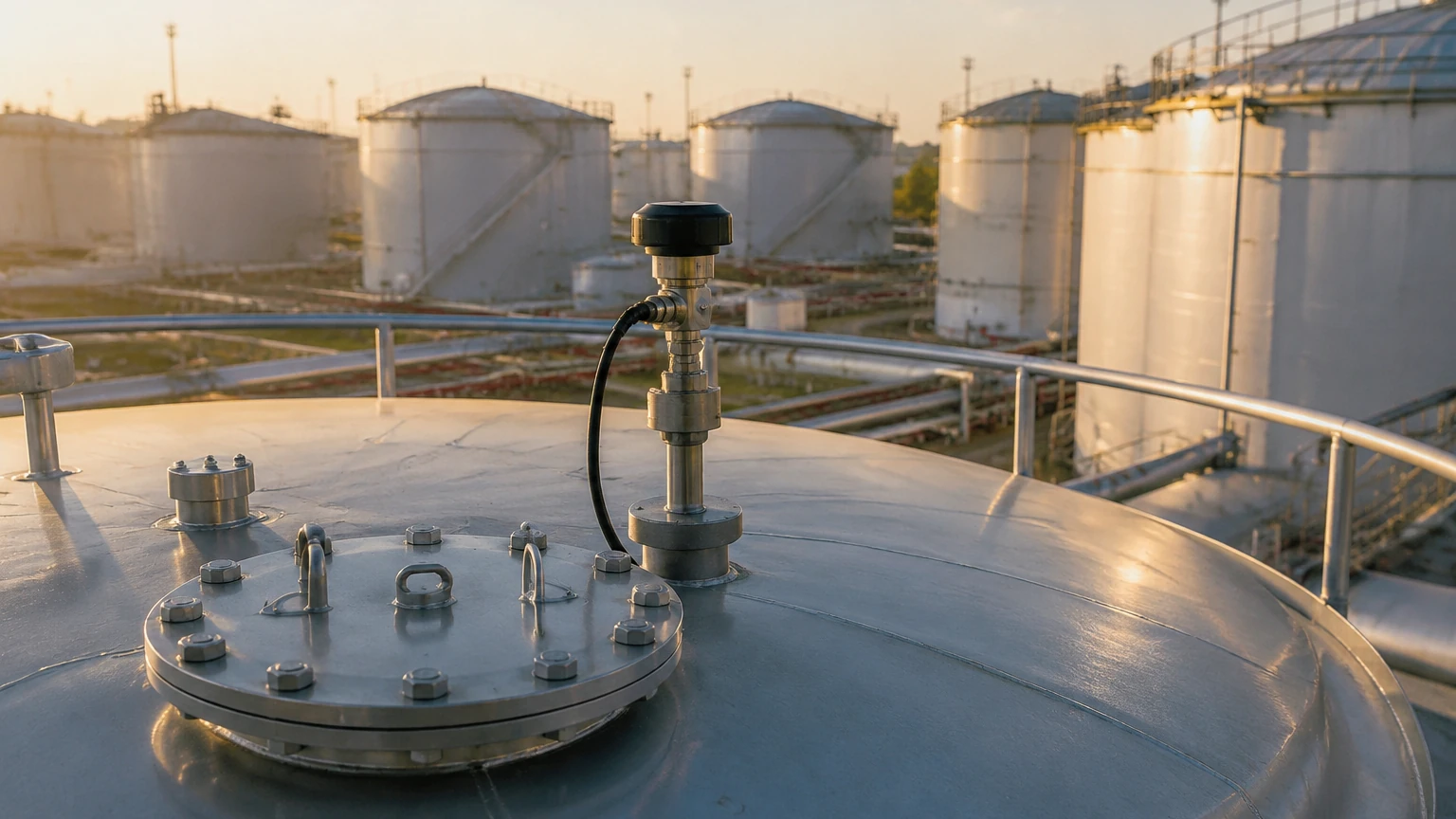
Practical Installation Guidelines
Correct installation is as important as sensor selection. Even the most advanced fuel tank level sensors will fail to provide accurate data if positioned incorrectly.
1. Avoid the Center: For non-contact sensors (Radar and Ultrasonic), do not mount the sensor in the exact center of a tank with a domed top. This can cause multiple reflections that confuse the signal processing unit.
2. The 1/3 Rule: A common engineering practice is to mount the sensor at a distance of 1/3 the tank radius from the outer wall. This typically provides a clear path to the fuel surface while avoiding wall interference.
3. Nozzle Height: If using a mounting nozzle, ensure the sensor's antenna or transducer face extends slightly past the bottom of the nozzle. If the sensor is recessed too far, the nozzle walls will create significant interference (ringing).
4. Stilling Wells: In tanks with heavy turbulence or surface foam, installing the sensor inside a stilling well (a vertical pipe with vent holes) can stabilize the liquid surface and provide a much cleaner signal.
5. Vertical Alignment: For all top-down sensors, the device must be mounted perfectly vertical. A tilt of even a few degrees can cause the signal to bounce away from the receiver, especially in tall tanks.
Limitations and Operational Risks
Engineers must be aware of the inherent risks associated with fuel level monitoring to implement effective redundancy and maintenance schedules.
* Vapor and Condensation: Fuel tanks experience significant temperature swings between day and night. This leads to condensation on the sensor face. While many modern radar sensors use drip-off lens designs to mitigate this, ultrasonic sensors may fail completely if water droplets block the transducer.
* Paraffin/Wax Buildup: In cold climates, diesel fuel can develop paraffin wax crystals. These crystals can coat the probes of GWR sensors or the diaphragms of hydrostatic sensors, leading to signal drift or "frozen" readings.
* Overfill Prevention: Level sensors used for inventory management should not be the sole means of overfill protection. Safety regulations (such as API 2350) often require a separate, independent high-level switch (e.g., a tuning fork or float switch) to trigger an emergency shut-off.
Frequently Asked Questions (FAQs)
Q: Can I use the same sensor for diesel and gasoline?
A: While the measurement principle may be the same, the hardware requirements differ. Gasoline is much more volatile and typically requires Explosion-Proof (Ex d) or Intrinsically Safe (Ex i) certifications. Additionally, the seal materials (O-rings) must be compatible with the specific aromatic hydrocarbons in gasoline.
Q: How does tank pressure affect the sensor?
A: Hydrostatic sensors are highly sensitive to tank pressure. If the tank is pressurized (not vented), a differential pressure transmitter must be used to subtract the headspace pressure from the total bottom pressure. Radar and magnetic gauges are generally unaffected by pressure changes up to their rated limits.
Q: What is the maintenance cycle for fuel level sensors?
A: For non-contact sensors in clean fuel, annual inspection is usually sufficient. Submersible sensors or GWR probes in heavy fuel oil or crude may require quarterly cleaning to remove buildup or sediment.
Q: Is it possible to measure the interface between fuel and water?
A: Yes. Water often settles at the bottom of fuel tanks. Guided Wave Radar is particularly adept at measuring both the top fuel level and the fuel-water interface, provided the upper liquid (fuel) has a lower dielectric constant than the lower liquid (water).
By understanding these technical nuances, B2B procurement and engineering teams can select fuel tank level sensors that provide the accuracy and longevity required for industrial fuel management. Proper selection reduces the risk of fuel run-outs, prevents environmental contamination from overfills, and ensures that inventory data remains a reliable asset for the organization.