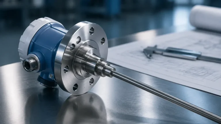
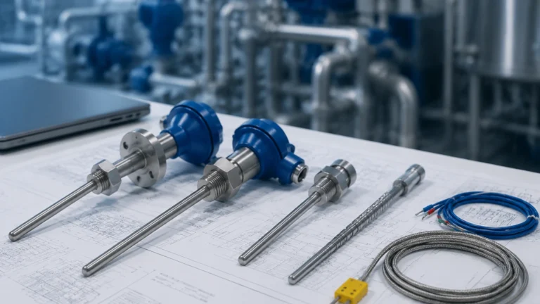
Fuel Tank Level
Fuel Tank Level
Accurate monitoring of fuel tank level is a cornerstone of industrial efficiency, safety, and environmental compliance. Whether managing bulk storage for diesel generators, aviation fuel at a regional airport, or heavy fuel oil (HFO) for maritime applications, the ability to measure liquid volume precisely prevents costly overfills, ensures operational continuity, and detects potential leaks early.
In the B2B sector, selecting a measurement technology requires a deep understanding of the physical properties of the fuel, the geometry of the storage vessel, and the environmental conditions of the site. This guide provides a technical overview of the primary measurement principles, selection criteria, and installation best practices for industrial fuel level monitoring.
Fundamental Principles of Fuel Level Measurement
Before selecting a specific instrument, it is essential to understand the physics behind the most common measurement methods. Industrial level sensors generally fall into two categories: contact and non-contact.
Hydrostatic Pressure Measurement
Hydrostatic level transmitters measure the pressure exerted by the liquid column at the bottom of the tank. The relationship is defined by the formula:
P = ρ × g × h
Where *P* is pressure, *ρ* (rho) is the density of the fuel, *g* is gravity, and *h* is the height of the liquid.
Because fuel density varies with temperature, hydrostatic sensors often require temperature compensation to maintain accuracy. This method is highly reliable for vented (atmospheric) tanks but requires a differential pressure setup for pressurized vessels.
Ultrasonic (Time-of-Flight)
Ultrasonic sensors emit high-frequency sound pulses that travel through the air, reflect off the fuel surface, and return to the transducer. The sensor calculates the distance based on the time taken for the echo to return. While cost-effective and non-contact, ultrasonic waves are sensitive to air temperature, pressure fluctuations, and heavy vapors, which are common in volatile fuels like gasoline.
Radar (Radio Detection and Ranging)
Radar sensors use electromagnetic waves (typically in the 26GHz or 80GHz range) rather than sound. Like ultrasonic sensors, they use time-of-flight, but radar waves are unaffected by air temperature, vacuum, or high pressure. For fuel tank level applications, radar is often preferred because it can penetrate vapors and provide millimeter-level precision. Radar can be non-contact or "guided wave" (using a probe to direct the signal).
Magnetic Level Gauges and Switches
Magnetic gauges utilize a float containing an internal magnet that moves with the fuel level inside a bypass chamber. Outside the chamber, magnetic flags or a transmitter track the float’s position. This provides a clear visual indication without requiring power, making it a favorite for safety-critical backup systems.
Comparison of Technologies for Fuel Tank Level Monitoring
Choosing the right technology depends on the specific requirements of the application, including accuracy needs, budget, and the physical properties of the fuel. The following table summarizes the key characteristics of the most common sensors used in the industry.
| Technology | Accuracy | Measurement Range | Suitability for Volatile Fuels | Maintenance Needs |
| :— | :— | :— | :— | :— |
| Radar (80GHz) | ±1 mm to ±2 mm | Up to 30m+ | Excellent (Unaffected by vapor) | Very Low |
| Guided Wave Radar | ±2 mm | Up to 20m | Excellent (Ignores foam) | Low |
| Hydrostatic | ±0.1% to 0.5% | Dependent on probe | Good (Requires density correction) | Medium (Probe cleaning) |
| Ultrasonic | ±0.25% of range | 0.5m to 15m | Poor (Vapors distort signal) | Low |
| Magnetic Gauge | ±5 mm | 0.3m to 6m | Good (Isolated from process) | Medium (Moving parts) |
For engineers seeking detailed technical specifications and data sheets for these technologies, the Main Page of industrial equipment providers offers a comprehensive starting point for comparing model-specific performance metrics.
Selection Criteria Based on Fuel Type and Tank Configuration
Not all fuels behave the same way under storage. The chemical and physical properties of the medium dictate the hardware requirements.
1. Diesel and Light Oils
Diesel is relatively stable and has a consistent density. Hydrostatic pressure sensors are frequently used for underground storage tanks (USTs) due to their ease of installation. However, for large above-ground storage tanks (ASTs), non-contact radar is the preferred choice to avoid contact with the medium and simplify maintenance.
2. Gasoline and Volatile Organic Compounds (VOCs)
Gasoline produces significant vapor, especially in warm climates. Ultrasonic sensors are generally unsuitable here because the vapor changes the speed of sound, leading to significant errors. Furthermore, these environments require ATEX or IECEx certified explosion-proof equipment. Radar is the gold standard for gasoline fuel tank level measurement due to its immunity to vapor and high-frequency precision.
3. Heavy Fuel Oil (HFO) and Bitumen
These fluids are highly viscous and often stored at elevated temperatures to maintain flow. Contact sensors like hydrostatic probes may suffer from coating or clogging. In these cases, high-temperature non-contact radar or magnetic level gauges with heating jackets are recommended.
4. Tank Geometry and Obstructions
Internal tank structures such as heating coils, baffles, or ladders can interfere with sensor signals. Modern radar sensors with narrow beam angles (such as 80GHz models) can "see" past these obstructions. If the tank is extremely narrow or has a complex internal structure, Guided Wave Radar (GWR) is often the best solution as the signal is confined to the probe.
Installation Best Practices and Engineering Considerations
Correct installation is as important as selecting the right sensor. Even the most advanced radar will fail if positioned incorrectly.
* Nozzle Positioning: Sensors should not be installed in the center of a tank (to avoid multiple reflections from the tank walls) or too close to the wall (to avoid signal interference). Ideally, the sensor should be placed at 1/4 to 1/3 of the tank diameter from the wall.
* Avoiding Turbulence: If the tank has an agitator or a high-velocity fill pipe, the fuel surface may be turbulent. This can cause signal scattering. Using a stilling well or a bypass pipe can provide a calm surface for accurate measurement.
* Venting and Pressure: For hydrostatic sensors, ensure the atmospheric vent is clear. If the tank is pressurized, a differential pressure (DP) transmitter must be used to subtract the head pressure from the liquid pressure.
* Dead Zones: Every sensor has a "dead zone" or "blocking distance" at the very top (near the sensor face) where it cannot measure. Ensure the tank’s maximum fill level does not enter this zone to avoid signal loss.
Limitations and Mitigation Strategies
While modern instrumentation is highly robust, certain physical limitations must be managed:
* Dielectric Constant (εr): Radar signals reflect off the surface based on the fuel's dielectric constant. Fuels like diesel have a low dielectric constant (~2.1), which reflects less energy than water (~80). Using a high-sensitivity radar or a guided wave system mitigates this issue.
* Temperature Extremes: High temperatures can affect sensor electronics. In extreme cases, use remote-mounted electronics or cooling fins to protect the transducer.
* Foaming: Some fuels may foam during high-speed filling. Ultrasonic sensors will fail in these conditions. Radar can typically penetrate light foam, but Guided Wave Radar is the most reliable choice for heavy foam applications.
Frequently Asked Questions (FAQ)
Q: How often should fuel tank level sensors be calibrated?
A: For commercial custody transfer, annual calibration is often mandated. For internal inventory management, a check every 12 to 24 months is usually sufficient, depending on the technology used. Radar sensors typically have much lower drift than hydrostatic sensors.
Q: Can one sensor measure both fuel level and water interface?
A: Yes. Water often settles at the bottom of fuel tanks. Guided Wave Radar (GWR) probes can detect both the fuel surface and the fuel-water interface because of the different dielectric constants of the two liquids.
Q: What is the impact of tank shape on volume calculation?
A: Most modern transmitters allow users to input a "strapping table" or select a tank shape (e.g., horizontal cylinder with dished ends). The sensor then converts the measured height into an accurate volume reading (liters or cubic meters) automatically.
Q: Are wireless level sensors reliable for fuel farms?
A: Yes, WirelessHART or LoRaWAN level sensors are increasingly common in large fuel farms where wiring costs are prohibitive. They offer high reliability provided the site has a well-designed mesh network or gateway coverage.
Conclusion
Managing fuel tank level effectively requires a balance between precision, reliability, and cost. While hydrostatic sensors remain a staple for simple diesel storage, the industry is rapidly shifting toward 80GHz radar for its superior accuracy and maintenance-free operation. By considering the specific dielectric properties of the fuel, the physical constraints of the tank, and the environmental safety requirements, engineers can implement a monitoring solution that ensures both operational safety and economic efficiency.
For technical assistance in selecting specific instrumentation or to view detailed product configurations, professionals are encouraged to visit the Main Page for further engineering resources and application support.