Gas Flow Analyzer
Gas Flow Analyzer
In industrial process control, the precise measurement of gas movement is essential for safety, efficiency, and environmental compliance. A gas flow analyzer (or gas flow meter) serves as the primary instrument for determining the mass or volumetric flow rate of gases through a closed conduit. Whether managing compressed air in a manufacturing plant, monitoring flare gas in a refinery, or controlling aeration in water treatment, selecting the correct measurement technology is a prerequisite for operational stability.
While level measurement instruments, such as those found on our Main Page, focus on the inventory within tanks and vessels, gas flow analyzers focus on the dynamics of the medium in transit. Together, these instruments provide the comprehensive data required for mass balance and process automation.
Understanding Gas Flow Measurement Principles
Before selecting a gas flow analyzer, it is necessary to understand the physical principles that govern different sensor types. Gas, unlike liquid, is highly compressible, meaning its volume changes significantly with variations in temperature and pressure. Therefore, measurement principles are generally categorized into volumetric flow and mass flow.
Thermal Mass Flow Principle
Thermal mass flow analyzers operate on the principle of heat transfer. The sensor typically consists of two RTD (Resistance Temperature Detector) elements. One serves as a reference, measuring the ambient gas temperature, while the other is heated to a specific temperature above the ambient. As gas flows past the heated sensor, it carries away heat. The instrument measures the electrical power required to maintain the temperature differential. Since heat dissipation is directly related to the number of gas molecules (mass), this method provides a direct mass flow reading without requiring separate pressure or temperature compensation.
Differential Pressure (DP) Principle
Based on Bernoulli’s equation, DP flow meters create a restriction in the pipe (such as an orifice plate, Venturi tube, or Pitot tube) to generate a pressure drop. The square root of the pressure difference between the upstream and downstream sides is proportional to the flow velocity. For gas applications, DP systems require additional sensors for pressure and temperature to calculate the compensated flow rate, as gas density varies with process conditions.
Vortex Shedding Principle
When a gas flows past a non-streamlined "bluff body" placed in the flow stream, it creates alternating vortices (swirls) known as the Karman Vortex Street. The frequency at which these vortices are shed is directly proportional to the velocity of the gas. Vortex flow meters are highly durable and have no moving parts, making them suitable for high-velocity steam and gas applications.
Ultrasonic Transit-Time Principle
Ultrasonic gas flow analyzers use acoustic transducers to send sound pulses diagonally across the pipe. The time taken for the pulse to travel with the flow is compared to the time taken against the flow. The difference in transit time is proportional to the gas velocity. This technology is often used for high-accuracy custody transfer and flare gas monitoring because it offers a wide turndown ratio and creates zero pressure drop.
Key Evaluation Criteria for Selecting a Gas Flow Analyzer
Choosing the right analyzer requires a detailed analysis of the process environment. Engineers must evaluate the following factors to ensure long-term reliability:
1. Gas Composition: Is the gas a single component (e.g., pure Nitrogen) or a complex mixture (e.g., Natural Gas or Biogas)? Thermal mass meters require specific calibration for the gas's thermal conductivity, whereas ultrasonic or vortex meters are less sensitive to composition changes but may require density inputs.
2. Flow Range and Turndown Ratio: The turndown ratio is the ratio between the maximum and minimum measurable flow. If a process has high seasonal or operational variability, a high turndown ratio (e.g., 100:1) is necessary. Thermal mass meters excel at low-flow detection, while vortex meters may have a "low-flow cut-off" where they cannot detect slow-moving gas.
3. Process Conditions: High-temperature gases (above 250°C) or high-pressure lines (above 40 bar) limit the choice of sensors. Materials of construction, such as 316L stainless steel or Hastelloy, must be selected based on the corrosivity of the gas.
4. Accuracy and Repeatability: For internal process control, a 2% to 5% accuracy might suffice. However, for billing or custody transfer, accuracies of 0.5% to 1.0% are typically mandated.
Practical Selection Table for Industrial Gas Flow
The following table provides a general comparison of common gas flow analyzer technologies used in industrial automation.
| Technology | Primary Measurement | Best Suited For | Typical Turndown | Pressure Drop |
| :— | :— | :— | :— | :— |
| Thermal Mass | Mass Flow | Compressed air, inert gas, low flow | 100:1 | Negligible |
| Vortex | Volumetric Flow | Steam, high-velocity gas | 20:1 | Medium |
| Ultrasonic | Volumetric Flow | Natural gas, flare gas, large pipes | 50:1 to 100:1 | Zero |
| Differential Pressure | Volumetric Flow | Clean gas, stable processes | 5:1 to 10:1 | High |
| Coriolis | Mass Flow | High-precision chemical dosing | 20:1 | Medium |
Installation Guidelines and Best Practices
Even the most advanced gas flow analyzer will fail to provide accurate data if installed incorrectly. Gas flow profiles must be fully developed (laminar) before reaching the sensor.
Straight Pipe Run Requirements
Most flow meters require a specific length of straight pipe upstream and downstream of the installation point to eliminate turbulence caused by elbows, valves, or reducers. A common rule of thumb is 10 to 20 diameters (D) upstream and 5D downstream. If space is limited, flow conditioners or honeycombs can be installed to straighten the flow profile.
Orientation and Positioning
For gas applications, sensors should ideally be installed on the top or side of a horizontal pipe. This prevents moisture (condensate) or particulates from settling on the sensor head, which is a frequent cause of measurement drift in thermal mass and ultrasonic units. In vertical pipes, the flow should ideally be upward to ensure any entrained liquids do not accumulate at the sensor site.
Safety and Certification
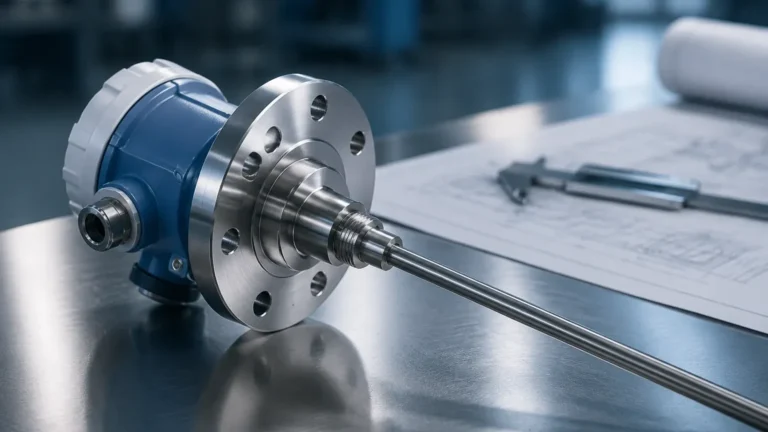
In industries such as oil and gas or chemical processing, gas flow analyzers must often be installed in hazardous areas. Ensure the device carries the appropriate ATEX, IECEx, or UL certifications for the specific zone (e.g., Zone 0 or Zone 1). Furthermore, for pressurized lines, the use of "hot tap" or "retractable" probes allows for maintenance without shutting down the entire process line.
Limitations and Common Risks in Gas Flow Monitoring
Understanding the limitations of these instruments prevents costly errors during the commissioning phase:
* Moisture and Condensate: In "wet" gas applications (like biogas or untreated compressed air), water droplets can hit a thermal mass sensor and cause significant spikes in the reading as the water evaporates. In such cases, moisture separators or heated sensors are required.
* Gas Composition Shifts: If a thermal mass meter is calibrated for 100% Nitrogen but the process gas changes to include 10% Hydrogen, the reading will be wildly inaccurate because Hydrogen has a much higher thermal conductivity. Frequent gas analysis or the use of multivariable DP meters may be necessary.
* Pressure Drop: DP-based meters create a permanent pressure loss in the system. In low-pressure systems, this can reduce the efficiency of the entire process or require larger pumps/compressors to compensate.
Synergy Between Flow and Level Measurement in Process Systems
In many industrial applications, gas flow analyzers work in tandem with level measurement technologies. For example, in a pressurized gas storage sphere, a radar level meter (available via our Main Page) monitors the liquid-gas interface, while a gas flow analyzer monitors the discharge rate.
By integrating both data points into a PLC or DCS, operators can perform real-time leak detection. If the level in the tank is dropping faster than the flow analyzer reports gas leaving the system, it indicates a potential breach in the vessel or piping. This holistic approach to instrumentation—combining flow, level, and pressure—is the foundation of modern industrial safety and efficiency.
Frequently Asked Questions (FAQ)
Q: Can I use a gas flow analyzer for steam?
A: Yes, but only specific types. Vortex shedding meters are the industry standard for steam because they can handle high temperatures and velocities. Thermal mass meters are generally not suitable for steam due to the phase-change nature of the medium.
Q: What is the difference between Normal (Nm³/h) and Standard (Sm³/h) units?
A: These refer to flow rates corrected to specific reference temperatures and pressures. "Normal" typically refers to 0°C and 1.013 bar, while "Standard" often refers to 15°C or 20°C. It is critical to confirm the reference conditions when comparing analyzer specifications.
Q: How often should a gas flow analyzer be calibrated?
A: This depends on the technology and the gas. For clean, inert gases, a biennial (every 2 years) check is often sufficient. For corrosive or "dirty" gases, annual calibration or even quarterly sensor cleaning may be required to maintain accuracy.
Q: Do I need a flow computer?
A: If you are using a volumetric meter (like Vortex or DP) and need mass flow data, a flow computer is necessary to integrate the pressure and temperature inputs. Modern "multivariable" transmitters often have this functionality built directly into the analyzer head.
For more information on integrating these sensors with your existing level measurement infrastructure, please visit our Main Page to explore our range of industrial instrumentation solutions.