Well Pressure Transducer
Well Pressure Transducer
In the field of industrial level measurement, the well pressure transducer—often referred to as a hydrostatic level transmitter—serves as a critical component for monitoring water levels in boreholes, deep wells, and reservoirs. Unlike surface-based ultrasonic or radar sensors, these instruments are designed to operate submerged, providing continuous data that is essential for resource management, pump control, and environmental monitoring. For engineers and facility managers, understanding the underlying physics and selection criteria for these devices is paramount to ensuring long-term reliability in demanding subsurface environments.
Understanding the Hydrostatic Measurement Principle
The operation of a well pressure transducer is based on the principle of hydrostatic pressure. According to Pascal's Law, the pressure at a specific point within a static liquid is directly proportional to the height of the liquid column above that point, the density of the liquid, and the force of gravity.
The mathematical relationship is expressed as:
P = ρ × g × h
Where:
* P is the hydrostatic pressure (measured in Pascals or bar).
* ρ (rho) is the density of the liquid (e.g., approximately 1,000 kg/m³ for water).
* g is the acceleration due to gravity (9.81 m/s²).
* h is the height of the liquid column (the depth).
In a well application, the transducer is lowered to a fixed depth. As the water level rises, the pressure exerted on the internal sensing diaphragm increases. The transducer converts this mechanical pressure into an electrical signal (typically 4-20mA or a digital protocol like RS485 Modbus). Since gravity and density are generally constants in a stable well environment, any change in the electrical signal corresponds directly to a change in the water level.
Atmospheric Pressure Compensation
One of the most critical aspects of using a well pressure transducer is compensating for atmospheric pressure. Changes in weather can cause significant fluctuations in barometric pressure, which would be interpreted by a sealed sensor as a change in water level. To solve this, high-quality well transducers use a vented cable. This cable contains a small capillary tube that allows the back of the sensing diaphragm to be exposed to the current atmospheric pressure, effectively "zeroing out" the barometric influence and ensuring the sensor only measures the pressure of the water column.
Key Components and Design
A professional-grade well pressure transducer, such as those discussed on our Main Page, consists of several specialized components engineered for submersion:
1. Sensing Element: Most modern units utilize a piezoresistive silicon sensor or a ceramic thick-film sensor. Silicon sensors offer high sensitivity and accuracy, while ceramic sensors provide excellent chemical resistance and durability against mechanical shock.
2. Housing: The outer shell is typically constructed from 316L stainless steel. For brackish water or chemical applications, materials like Titanium or Hastelloy are used to prevent corrosion.
3. Diaphragm: A thin, flexible membrane that isolates the internal electronics from the fluid while transferring pressure to the sensing element.
4. Vented Cable: A rugged, waterproof cable (often Polyurethane or FEP) that provides power, signal transmission, and atmospheric venting.
5. Signal Conditioner: Internal electronics that amplify the raw sensor signal and provide temperature compensation to maintain accuracy across varying well temperatures.
Selection Criteria for Industrial Well Applications
Choosing the right well pressure transducer requires a detailed analysis of the well's physical characteristics and the fluid's properties. Engineering teams should evaluate the following parameters:
Measurement Range and Accuracy
It is vital to select a transducer with a pressure range that closely matches the maximum expected water depth. Using a 100-meter sensor in a 10-meter well will result in poor resolution. Standard accuracy for industrial units ranges from ±0.5% to ±0.1% of the full scale.
Material Compatibility
While 316L stainless steel is standard for clean water, it may fail in the presence of high chlorides or acidic conditions. In such cases, specialized coatings or alternative alloys must be specified. The cable material is equally important; Polyurethane (PUR) is excellent for general use, while Fluorinated Ethylene Propylene (FEP) is required for wells containing hydrocarbons or aggressive chemicals.
Output Signal
* 4-20mA Analog: The industry standard for long-distance transmission (up to 1,000 meters) with high noise immunity.
* RS485/Modbus RTU: Ideal for digital integration, allowing for multiple sensors on a single bus and the transmission of diagnostic data (e.g., internal temperature).
* 0-5V / 0-10V: Generally reserved for short-distance applications or battery-powered data loggers.
Comparison of Sensor Technologies
| Feature | Piezoresistive Silicon | Ceramic Capacitive | Strain Gauge |
| :— | :— | :— | :— |
| Sensitivity | Very High | High | Moderate |
| Overpressure Resistance | Moderate | Excellent | Good |
| Chemical Stability | Requires Oil Filling | Excellent (Dry Cell) | Good |
| Long-term Drift | Very Low | Low | Moderate |
| Typical Applications | Deep wells, clean water | Wastewater, slurry | Heavy industrial tanks |
Installation Best Practices and Field Considerations
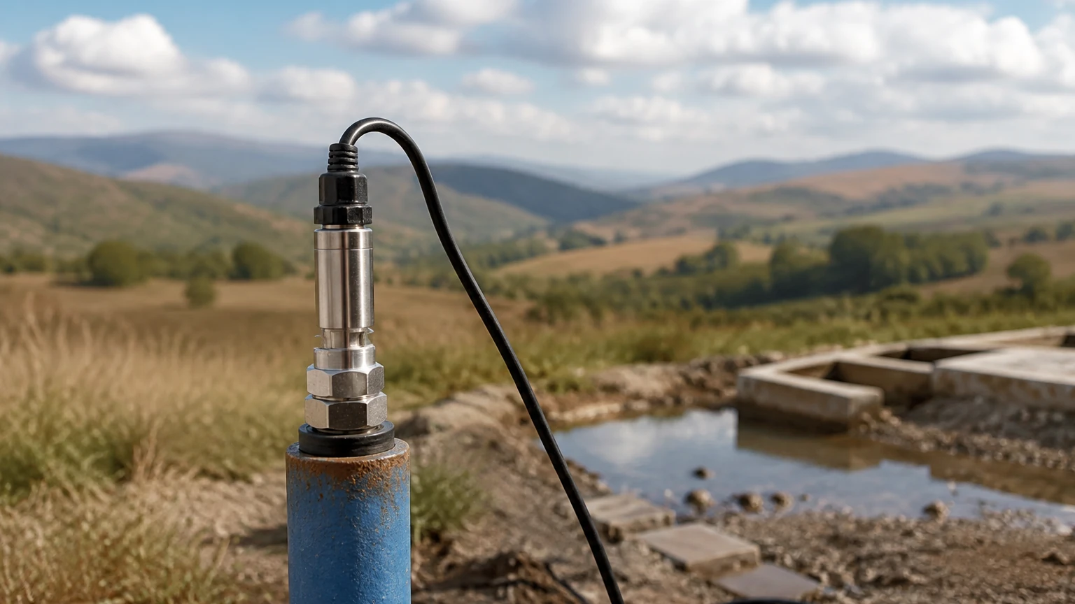
Proper installation is the single most important factor in the longevity of a well pressure transducer. Even the highest quality instrument will fail if subjected to improper mechanical stress or environmental ingress.
1. Cable Support and Strain Relief
The weight of the cable in a deep well can be substantial. A dedicated cable clamp or "Kellems grip" should be used at the wellhead to support the cable weight, preventing the internal wires and the vent tube from being stretched or kinked.
2. Preventing Moisture Ingress
The atmospheric vent tube in the cable is a potential entry point for moisture. If water vapor enters the tube and condenses inside the sensor housing, it will destroy the electronics. Every installation should include a desiccant filter (drying cartridge) at the end of the vent tube. This filter must be inspected and replaced periodically as it becomes saturated.
3. Turbulence and Physical Protection
In wells with high-flow pumps, turbulence can cause the transducer to swing, leading to mechanical wear or erratic readings. Installing the transducer inside a "stilling well" (a perforated PVC or steel pipe) will stabilize the sensor and protect it from debris.
4. Lightning and Surge Protection
Because well transducers are connected to long lengths of cable, they are susceptible to induced surges from lightning strikes. Integrated surge protection within the transducer and additional lightning arrestors at the control panel are highly recommended for outdoor installations.
Limitations and Environmental Factors
While the well pressure transducer is a versatile tool, engineers must be aware of its inherent limitations:
* Density Sensitivity: Since the measurement is based on weight, changes in fluid density (e.g., due to salinity changes or temperature shifts) will introduce errors. If the fluid density changes significantly, the system must be recalibrated or use a density-compensated algorithm.
* Sediment Accumulation: In wells with high silt content, sediment can build up around the diaphragm, blocking the pressure ports. Periodic cleaning or the use of a "flush diaphragm" design may be necessary.
* Temperature Extremes: Although the transducer is submerged and usually insulated by the surrounding earth, the electronics have specific operating ranges (typically -20°C to +80°C). Standard units are not suitable for geothermal wells without specialized cooling or high-temperature construction.
Frequently Asked Questions (FAQ)
Q: How often should a well pressure transducer be calibrated?
A: For most industrial applications, an annual calibration check is recommended. However, in critical environmental monitoring, semi-annual checks may be required to account for any long-term sensor drift.
Q: Can I cut the cable of a well pressure transducer to fit my depth?
A: It depends on the model. Many vented cables are factory-sealed. Cutting the cable requires specialized re-termination to ensure the vent tube remains open and the waterproof seal is maintained. It is generally better to order the specific length required or coil the excess neatly at the surface.
Q: What is the maximum depth a well pressure transducer can measure?
A: Standard industrial models can measure depths up to 500 meters (approx. 50 bar). Custom high-pressure versions are available for deeper boreholes, though signal attenuation and cable weight become significant engineering challenges at these depths.
Q: Does the sensor need to be at the very bottom of the well?
A: No. The sensor should be placed below the lowest expected water level (the drawdown level) but ideally a few meters above the bottom to avoid silt and mud accumulation.
For technical specifications and assistance in selecting the correct instrument for your specific project, please visit our Main Page to review product options and application support. Our engineering team provides customized OEM/ODM services to meet the unique requirements of water treatment, chemical processing, and industrial automation sectors worldwide.